
Yan Wu, Yang Yang, Yue Yin, Linmao Dai, Xiaochun Li, Huihui Huang, Shuangchun Wen, "Flexible high-resolution thin micropolarizers for imaging polarimetry," Chin. Opt. Lett. 21, 031301 (2023)
- Chinese Optics Letters
- Vol. 21, Issue 3, 031301 (2023)
Abstract
1. Introduction
Polarization imaging is one of the most important optical imaging types, which captures information about polarized light reflected or scattered by objects in a scene. This is conducive to analyzing the surface and material properties of objects and is used in remote sensing[1,2], biological imaging[3,4], and industrial monitoring[5–7]. Micrometer-sized patterned polarizers are coated on a metal-oxide-semiconductor (CMOS) camera to form a polarization imaging system to achieve polarization sensitivity[8–12].
For a high-performance polarized imaging system, polarizers with high extinction ratios are required. Besides the optical properties, the high resolution of the elements is also required in the imaging system. The high resolution can be pixel-aligned with the camera’s semiconductor device. In addition to enhancing system performance, the flexible ultrathin polarizer reduces the weight of the system and makes it easier to integrate, and another surprising advantage is that the ultrathin flexible optical element deforms without damage during bending.
A variety of patterned polarizers have been created, including metal wire grids[13,14], birefringent
Sign up for Chinese Optics Letters TOC. Get the latest issue of Chinese Optics Letters delivered right to you!Sign up now
Therefore, azo dye micropolarizers based on photoalignment technology have received increasing attention from researchers. Photoalignment technology is a simple, cost-effective, large-area fabrication technology. In the past, it has been studied to dope the azo dye as a guest material in the host material (liquid crystal monomer), and the azo dye will coordinate and arrange in the direction of the liquid crystal monomer[23].
Liquid crystal polymers (LCPs) with a well-controlled molecular positioning in all three dimensions attract considerable attention due to their unusual but very accurately adjustable and addressable optical, electrical, and mechanical properties[24–29]. Liquid crystal monomers are compounds that combine mesogens and reactive monomers. LCPs are formed by photocuring liquid crystal monomers. The alignment pattern of the liquid crystal monomers is preserved during the polymerization process. LCP as an emerging material developed by photo-alignment technology, has long-range order and excellent mechanical properties, and is a potential material for organizing the long-range ordered structure of azo dyes.
However, the traditional guest-host system has the following disadvantages. The photo-curing process leads to large-area disorder in the mixing of LCPs and azo dyes, which affects the preparation of high-precision patterns of azo dyes[30]. In addition, a disadvantage of homogeneous guest-host system polarizers is the complete miscibility of the dichroic dye and liquid crystal monomers, which may have limited solubility and result in phase separation[21,31]. This disadvantage makes the extinction ratio of dichroic dye polarizers only 10–100[21]. Recently, the work of Fan et al. has received attention for achieving broad-band polarization modulation by introducing a black dye to the liquid crystal system. In addition they achieved a high extinction ratio of 225 by increasing the thickness of the liquid crystal cassette (
Several high-resolution patterned polarizers based on the traditional guest-host system were fabricated[21,33]. Conventional guest-host systems achieve high-precision patterning by using a wire grid mask for UV-polarized light exposure. The process of using a wire grid mask in the visible range involves complex selective lithography processes. Jia et al. proposed
To solve the above problems, we propose a technique for fabricating flexible ultrathin high-resolution patterned polarizers by aligning azo dye molecules on LCPs. The LCP not only serves as an alignment layer for azo dyes, but also provides a flexible substrate for micropolarization. The dichroic polarizer has a polarization efficiency of 99.7%. Direct laser-writing technology enables the realization of a variety of complex microstructures in a simple, cost-effective way that eliminates the associated alignment errors associated with the reticle exposure step. A 2 µm flexible ultrathin patterned polarizer and 8 µm four-state microarray polarizers of 0°, 45°, 90°, and
2. Experiments and Methods
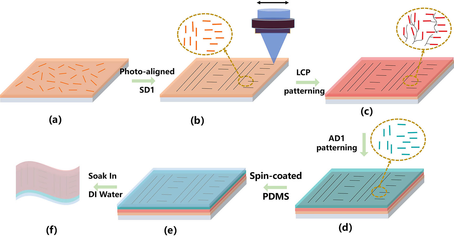
In this article, we demonstrate the detailed process of manufacturing flexible high-resolution patterned polarizers using noncontact light alignment technology, as shown in Fig. 1 and summarized as follows.
![]()
Figure 1.Schematic diagram of the preparation process of a flexible high-resolution patterned polarizer. (a) Photoalignment layer is spin-coated onto a quartz substrate. (b) Regions of the photoalignment layer are aligned using laser writing. (c) Liquid crystal precursor is spin-coated on top of SD1. (d) Spin-coated AD1s solution; (e) spin-coated PDMS; (f) flexible patterned polarizer.
Photo-alignment material SD1 is dissolved in dimethylformamide (DMF) at a concentration of 0.5% (mass fraction). A clean piece of glass is spin-coated with SD1 solution at 3000 r/min for 40 s [Fig. 1(a)], and the sample is placed at 100°C for 3 min. The designed profile is transferred to the transparent glass substrate with SD1 by a direct-writing system [Fig. 1(b)]. The minimum resolution of laser direct writing is 0.15 µm. The maximum exposure area is a circle with a diameter of 25 mm. Liquid crystal precursor of RM257 (95%, mass fraction) and photoinitiator 184 (5%) dissolved in toluene were spin-coated onto the patterned SD1 films at 4000 r/min for 30 s [Fig. 1(c)]. For the multilayer spin-coating process, the second layer of liquid crystal was spin-coated on top of the first LCP layer after it was polymerized by UV light curing. The upper layer can be made repeatedly through the spin coating and UV curing. The 5% solution of the dichroic dyes AD1 in toluene was prepared. The AD1 solution was spin-coated on the multilayer LCP film at 4000 r/min for 30 s [Fig. 1(d)]. Despite the inherent elasticity of LCP, it is difficult for very thin LCPs to be repeated many times. The polydimethylsiloxane (PDMS) has good mechanical flexibility, light transmittance, and stability, making it an excellent choice for flexible materials. PDMS was obtained by mixing Sylgard184 silicone elastomer with the curing agent in a ratio of 10:1 and then placing it in a vacuum for 30 min[35]. PDMS was spin-coated onto the azo dye layer at 1000 r/min for 30 s [Fig. 1(e)]. PDMS was cured at 120°C for 1 h. By curing the PDMS, the strong interfacial adhesion is created between the PDMS and the AD1/LCP layer, which is effective in separating the LCP from the glass substrate to form a flexible folded polarizer. The sample was placed in deionized water for 3 min to obtain a flexible patterned polarizer [Fig. 1(f)].
Extinction ratio and polarization are two important parameters to describe polarization performance. The extinction ratio is a metric of a polarizer’s attenuation efficiency for two orthogonal polarization states, and is defined in Eq. (1)[21],
3. Results and Discussion
We first investigated the influence of the guest-host system on the arrangement of azo dyes. To align the AD1 molecules, the SD1 film is illuminated by linearly polarized light. Figures 2(a) and 2(b) show photographs of the typical mixture film viewed between a pair of crossed polarizers. The LCP layer is uniformly aligned before photo-initiated polymerization in Fig. 2(a). After photocuring, the mixture of liquid crystal molecules and azo dyes is disordered in a large area, and two different arrangement regions appear in Fig. 2(b). This hinders the preparation of high-precision patterned polarizers.
![]()
Figure 2.Photograph of a mixture film of liquid crystal and azo dye observed between a pair of crossed polarizers. (a) Before UV curing and (b) after UV curing. The physical picture of the polarizer when the polarization direction of the analyzed polarizer is (c) 0° and (d) 90°. The arrow indicates the direction of polarization of the analyzed polarizer. (e) Surface topography of the AD1 thin film with a thickness of 700 nm; the RMS of the roughness in a 2 µm × 2 µm area is 0.205 nm. (f) Cross-sectional SEM image of the polarizer on a glass substrate.
Through the separation of LCPs and azo dye molecules, the disorder of molecular arrangement disappears. When the direction of the AD1 molecules is parallel to the polarizer axis [Fig. 2(c)], a perfectly bright state is obtained, which means that the optic axis of the molecular aggregates is parallel to the analyzer axis of the analyzed polarizer. By rotating the direction of polarization of the analyzed polarizer, the minimum brightness is achieved when the polarization direction of the polarizer is 90° [Fig. 2(d)]. The physical map shows that the arrangement and morphology of AD1 molecules on the LCP remain stable without any macroscopic perturbation of the morphology. AFM analysis is conducted to investigate the surface topology of the AD1 film on the fine-scale in Fig. 2(e). Its root mean square (RMS) roughness is estimated to be 0.205 nm. As expected, the patterned AD1 on the LCP substrate shows a relatively smooth surface morphology. To obtain a cross-sectional view of the structure, scanning electron microscopy (SEM) was used, as shown in Fig. 2(f). From the image, a uniform azo dye layer (700 nm) on top of the LCP (4.2 µm) could be observed. The number of layers of the test sample LCP is six.
To determine the polarized characteristics of the dichroic linear polarizer, its extinction ratio was tested. The test equipment is shown in Fig. 3(a). The light source wavelength was 450 nm. The transmitted light intensity is plotted in Fig. 3(b) as a function of the angular rotation of the analyzed polarization axis. It can be seen from Fig. 3(b) that when the polarization direction of the analytical polarizer is parallel to the AD1 molecular direction (0° and 180°), the transmittance reaches the maximum value, and when the polarization direction of the analytical polarizer is perpendicular to the AD1 molecular direction, the transmittance reaches a minimum value. The transmission extinction ratio for both polarization states is 336. The maximum polarization efficiency (PE) value of 99.7% at 450 nm, indicates that this film can be used as a linear polarizer.
![]()
Figure 3.(a) Extinction ratio test equipment for the dichroic-oriented polarizer. (b) Transmitted light intensity dependence on the rotation angle of the analyzing polarizer shows an extinction ratio of 336:1 for the aligned AD1, as indicated by the blue diamonds, with solid lines representing the cos2 fit. (c) Extinction ratio of polarizer versus number of LCP layers.
We found that the extinction ratio of the azo dye polarizer is related to the thickness of the LCP. Figure 3(c) shows that the extinction ratio of AD1 increases with the number of LCP layers and then saturates. The extinction ratio is 336 when the number of LCP layers is five.
We compared microscopic polarized optical images of AD1 unidirectionally arranged with different LCP layer numbers [Figs. 4(a)–4(f)], all other conditions being kept the same. When the number of LCP layers is one, the surface of the azo dye film shows a schlieren texture, indicating a slightly random arrangement of molecular order and showing the presence of light leakage in the blank areas, as shown in Fig. 4(a). The polarizer with more than three LCP layers has a uniform surface, and the light leakage feature disappears in Figs. 4(c)–4(f). This indicates that the order of azo dye molecules on LCP films with more than three layers is higher than that on one layer. The thickness of the three-layer LCP is about 2 µm. The experimental results of optical microscopy are consistent with the results of the extinction ratio test. The experimental results show that the polarization efficiency of the dichroic dye polarizing film strongly depends on the order parameters of the dichroic dye, and the order parameters are affected by the number of layers of the LCP. These results illustrate that when the AD1 solution concentration is too large, the anchoring strength of the one LCP layer to the AD1 interface is insufficient to maintain the molecular distribution in the region near the AD1–air interface. The multi-liquid crystal polymer layers enhance the molecular interactions between LCP and azo dyes. During spin coating, the number of liquid crystal mesogens is regulated by the concentration of the liquid crystal precursor solution and the rotational speed. Obviously, by tuning concentration and rotational speed, the corresponding extinction ratio can be freely tailored.
![]()
Figure 4.Polarized optical microscope image of azo dye film on (a) one LCP layer; (b) two LCP layers; (c) three LCP layers; (d) four LCP layers; (e) five LCP layers; (f) six LCP layers, respectively. Scale bar, 100 µm.
The accuracy of the pattern has an important influence on the application of the patterned linear polarizer. The 2 µm grating structure [Figs. 5(a)–5(d)] linear polarizer was realized. The direction of the azo dye in polarization grating can be described by
![]()
Figure 5.Microphotographs of the fabricated grating-structured polarizing film magnified 100 times, with (a) 0°, (b) 45°, (c) 90°, (d) 135° linear polarizer on top; scale bar, 2 µm. The yellow double arrows show the molecular orientation of the azo dye, and the black double arrows show the orientation of the analytical polarizer. Microphotographs of the fabricated checkerboard-structured polarizing film, with (e) 0° and (f) 90° linear polarizer on top.
We fabricated micropolarizer arrays capable of extracting all partial linear polarization information. A micropolarizer array with pixels [Figs. 5(e) and 5(f)] as small as
The optical properties after applying cyclic deformation are important to determine the mechanical durability of ultrathin flexible polarizers. The extinction ratio of the flexible polarizer at 450 nm was tested after 100 consecutive bends of 1 mm bending radius at 21°C and 43% humidity, as shown in the inset in Fig. 6(c). When the number of folds increases to 300, the extinction ratio decreases slightly, and then it stabilizes, as shown in Fig. 6(c). The small value of
![]()
Figure 6.Image of patterned AD1 on the bendable LCP film with (a) 0°, (b) 90°linear polarizer on top. (c) Normalized extinction ratio of the flexible polarizer versus the number of bending cycles at a radius of 1 mm, and the folding angle ranges from 180° AD1 (illustration on the left) to 0° (illustration on the right). The gray line represents the best fit.
Flexible high-resolution microarray devices have a high extinction ratio and an ultrathin thickness. The ultrathin thickness substantially reduces signal cross talk between adjacent pixels. These optical properties make it a strong candidate for polarization imaging systems. Such a film is quite thin: the surface has some adhesion so that it can be easily laminated to a CCD sensing surface and can be repeatedly integrated into the package multiple times. It also has potential use in a wide range of daily applications. It can be used as a flexible covert carrier of information to protect privacy, etc. Specific information is carried on dye-based molecular films that can only be recognized under microscopic or unique viewing conditions. They can be made into wearable devices. The polarizing thin film has a thickness of just 700 nm, compatible with flexible substrates, making it perfect for use as a dichroic polarizer in ultrathin and flexible displays to achieve more compact display systems. In summary, our approach opens up new possibilities for fabricating complex structures on the curved surface of polarization devices. The outstanding features of flexible structured polarization devices are flexibility and excellent optical properties, which can be used not only for conventional polarization imaging systems, but also have greater potential for integrated coupling with other new innovative devices.
4. Conclusion
In conclusion, we investigated the azo-dye-independent layering technique with an LCP. For more material-ordered designs, objects with complex structures need to be introduced into the liquid crystal order, such as various functional liquid crystal materials containing fullerenes,
References
[1] G. C. Giakos. Multifusion, multispectral, optical polarimetric imaging sensing principles. IEEE Trans. Instrum. Meas., 55, 1628(2006).
[2] J. S. Tyo, M. P. Rowe, E. N. Pugh, N. Engheta. Target detection in optically scattering media by polarization-difference imaging. Appl. Opt., 35, 1855(1996).
[3] J. Qi, C. He, D. S. Elson. Real time complete Stokes polarimetric imager based on a linear polarizer array camera for tissue polarimetric imaging. Biomed. Opt. Express, 8, 4933(2017).
[4] M. Garcia, C. Edmiston, R. Marinov, A. Vail, V. Gruev. Bio-inspired color-polarization imager for real-time in situ imaging. Optica, 4, 1263(2017).
[5] F. Goudail, P. Terrier, Y. Takakura, L. Bigué, F. Galland, V. DeVlaminck. Target detection with a liquid-crystal-based passive Stokes polarimeter. Appl. Opt., 43, 274(2004).
[6] M. P. Rowe, E. N. Pugh, J. S. Tyo, N. Engheta. Polarization-difference imaging: a biologically inspired technique for observation through scattering media. Opt. Lett., 20, 608(1995).
[7] S.-S. Lin, K. M. Yemelyanov, J. E. N. Pugh, N. Engheta. Polarization-based and specular-reflection-based noncontact latent fingerprint imaging and lifting. J. Opt. Soc. Am. A, 23, 2137(2006).
[8] N. A. Rubin, G. D’Aversa, P. Chevalier, Z. Shi, W. T. Chen, F. Capasso. Matrix Fourier optics enables a compact full-Stokes polarization camera. Science, 365, eaax1839(2019).
[9] N. Hosoya, T. Katsumata, I. Kajiwara, T. Onuma, A. Kanda. Measurements of S0 mode Lamb waves using a high-speed polarization camera to detect damage in transparent materials during non-contact excitation based on a laser-induced plasma shock wave. Opt. Lasers Eng., 148, 106770(2022).
[10] D. Gottlieb, O. Arteaga. Mueller matrix imaging with a polarization camera: application to microscopy. Opt. Express, 29, 34723(2021).
[11] X. Ma, F. Dong, Z. Zhang, Y. Su, T. Xu, Z. Jiang, S. Wu, Q. Zhang, W. Chu, X. Wu. Pixelated-polarization-camera-based polarimetry system for wide real-time optical rotation measurement. Sens. Actuators B Chem., 283, 857(2019).
[12] T. Kiire, T. Yatagai, S. Nakadate, M. Shibuya. Quadrature phase-shifting interferometer with a polarization imaging camera. Opt. Rev., 17, 210(2010).
[13] Y. Zhou, D. J. Klotzkin. Design and parallel fabrication of wire-grid polarization arrays for polarization-resolved imaging at 1.55 µm. Appl. Opt., 47, 3555(2008).
[14] S. Bernd, K. Ernst-Bernhard, W. Frank. Study on polarizing visible light by subwavelength-period metal-stripe gratings. Opt. Eng., 38, 220(1999).
[15] M. Momeni, A. H. Titus. An analog VLSI chip emulating polarization vision of octopus retina. IEEE Trans. Neural Networks, 17, 222(2006).
[16] J. Guo, D. Brady. Fabrication of thin-film micropolarizer arrays for visible imaging polarimetry. Appl. Opt., 39, 1486(2000).
[17] W.-L. Hsu, G. Myhre, K. Balakrishnan, N. Brock, M. Ibn-Elhaj, S. Pau. Full-Stokes imaging polarimeter using an array of elliptical polarizer. Opt. Express, 22, 3063(2014).
[18] W.-L. Hsu, K. Balakrishnan, M. Ibn-Elhaj, S. Pau. Infrared liquid crystal polymer micropolarizer. Appl. Opt., 53, 5252(2014).
[19] G. Myhre, W.-L. Hsu, A. Peinado, C. LaCasse, N. Brock, R. A. Chipman, S. Pau. Liquid crystal polymer full-Stokes division of focal plane polarimeter. Opt. Express, 20, 27393(2012).
[20] X. Zhao, A. Bermak, F. Boussaid, V. G. Chigrinov. Liquid-crystal micropolarimeter array for full Stokes polarization imaging in visible spectrum. Opt. Express, 18, 17776(2010).
[21] G. Myhre, A. Sayyad, S. Pau. Patterned color liquid crystal polymer polarizers. Opt. Express, 18, 27777(2010).
[23] G. H. Heilmeier, L. A. Zanoni. Guest-host interactions in nematic liquid crystals: a new electro-optic effect. Appl. Phys. Lett., 13, 91(1968).
[24] D. Liu, D. J. Broer. Liquid crystal polymer networks: preparation, properties, and applications of films with patterned molecular alignment. Langmuir, 30, 13499(2014).
[25] S. Huang, S. Luo, Y. Yang, T. Li, Y. Wu, Q. Zeng, H. Huang. Determination of optical rotation based on liquid crystal polymer vortex retarder and digital image processing. IEEE Access, 10, 8219(2022).
[26] T. Li, Y. Yang, X. Liu, Y. Wu, Y. Zhou, S. Huang, X. Li, H. Huang. Enhanced optical edge detection based on a Pancharatnam–Berry flat lens with a large focal length. Opt. Lett., 45, 3681(2020).
[27] Y. Wu, Y. Yang, T. Li, S. Huang, H. Huang, S. Wen. Stretchable and foldable waveplate based on liquid crystal polymer. Appl. Phys. Lett., 117, 263301(2020).
[28] Y. Yang, X. Liu, Y. Wu, T. Li, F. Fan, H. Huang, S. Wen. Optical edge detection with adjustable resolution based on liquid crystal polarization gratings. Chin. Opt. Lett., 18, 093501(2020).
[29] Y. Yin, Y. Yang, T. Li, Y. Zhou, Y. Wu, S. Huang, H. Huang. High-dynamic-resolution optical edge detection based on liquid crystal diffractive moiré lenses with a tunable focal length. Opt. Lett., 46, 2549(2021).
[30] E. Peeters, J. Lub, J. A. M. Steenbakkers, D. J. Broer. High-contrast thin-film polarizers by photo-crosslinking of smectic guest–host systems. Adv. Mater., 18, 2412(2006).
[31] R. J. Cox. Liquid crystal guest-host systems. Mol. Cryst. Liq. Cryst., 55, 1(1979).
[32] X.-Y. Fan, W.-Y. Ma, Y.-M. Zhang, C.-T. Xu, H. Ren, W.-M. Han, C.-Y. Chen, W. Hu. Broadband spatial polarization processing of light via a photopatterned dichroic medium. Appl. Phys. Lett., 120, 041103(2022).
[33] X. Zhao, F. Boussaid, A. Bermak, V. G. Chigrinov. High-resolution thin ‘guest-host’ micropolarizer arrays for visible imaging polarimetry. Opt. Express, 19, 5565(2011).
[34] J. Hao, Y. Wang, K. Zhou, X. Yu, Y. Yu. New diagonal micropolarizer arrays designed by an improved model in Fourier domain. Sci. Rep., 11, 5778(2021).
[35] Y. Arafat, I. Dutta, R. Panat. Super-stretchable metallic interconnects on polymer with a linear strain of up to 100%. Appl. Phys. Lett., 107, 081906(2015).


Set citation alerts for the article
Please enter your email address

© Copyright 2018-2021 | Chinese Laser Press. All Rights Reserved 沪ICP备15018463号-20