• Chinese Optics Letters
  • Vol. 15, Issue 9, 092701 (2017)
Ming Li1、2, Changling Zou1、2, Guangcan Guo1、2, and Xifeng Ren1、2、*
Author Affiliations
  • 1Key Laboratory of Quantum Information, CAS, University of Science and Technology of China, Hefei 230026, China
  • 2Synergetic Innovation Center of Quantum Information & Quantum Physics, University of Science and Technology of China, Hefei 230026, China
  • show less
    DOI: 10.3788/COL201715.092701 Cite this Article Set citation alerts
    Ming Li, Changling Zou, Guangcan Guo, Xifeng Ren. Effect of unbalanced and common losses in quantum photonic integrated circuits[J]. Chinese Optics Letters, 2017, 15(9): 092701 Copy Citation Text show less
    Eigenmodes of coupled waveguides. (a) A schematic of a directional coupler. (b) The cross-section electric field distributions of the eigenmodes for different cases. From the left column to right, the pictures correspond to the (i) ideal case γ1,=γ2, (ii) γ1≠γ2, and material 3 is lossless, (iii) γ1=γ2 and material 3 is absorptive. For the left and right case, the two eigenmodes are orthogonal and the overlap is zero. For the middle case, the overlap of the two modes is positive.
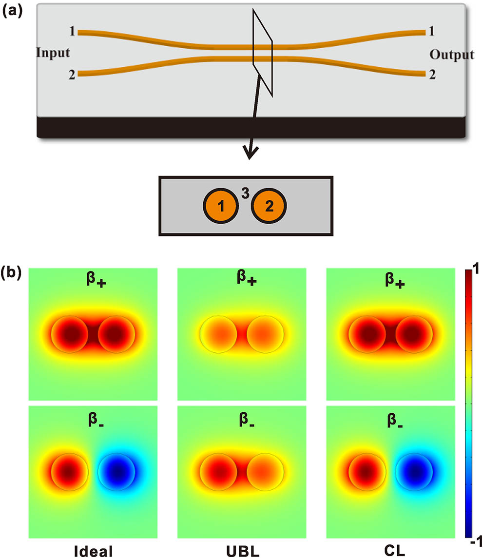
    Fig. 1. Eigenmodes of coupled waveguides. (a) A schematic of a directional coupler. (b) The cross-section electric field distributions of the eigenmodes for different cases. From the left column to right, the pictures correspond to the (i) ideal case γ1,=γ2, (ii) γ1γ2, and material 3 is lossless, (iii) γ1=γ2 and material 3 is absorptive. For the left and right case, the two eigenmodes are orthogonal and the overlap is zero. For the middle case, the overlap of the two modes is positive.
    (Color online) Two coupled waveguides with an unbalanced linear loss. (a) By injecting a single photon in port 1 in Fig. 1(a), the hopping probability to the outputs are plotted. Blue line: port 1. Red line: port 2. The inset shows the relative intensity eliminating the global damping factor. We set C=0.01k0 and Δγ=0.01k0. (b) The mode overlap |〈+|−〉|2 of the two eigenmodes. (c) The real (blue) and imaginary (red) part of the difference between β+ and β−. The cross point is the exceptional point. (d) L0 is the minimum coupling length to achieve 1:1 splitting. (e). Two-photon quantum interference visibility on an ideal BS with C=0.01k0. (f) Two-photon quantum interference visibility on a BS with unbalanced linear loss as a function of the coupling length. C=0.01k0 and Δγ=0.01k0. In all the figures, the units of C and γi are the free-space wave vector k0. We set C=0.01k0 for all the cases.
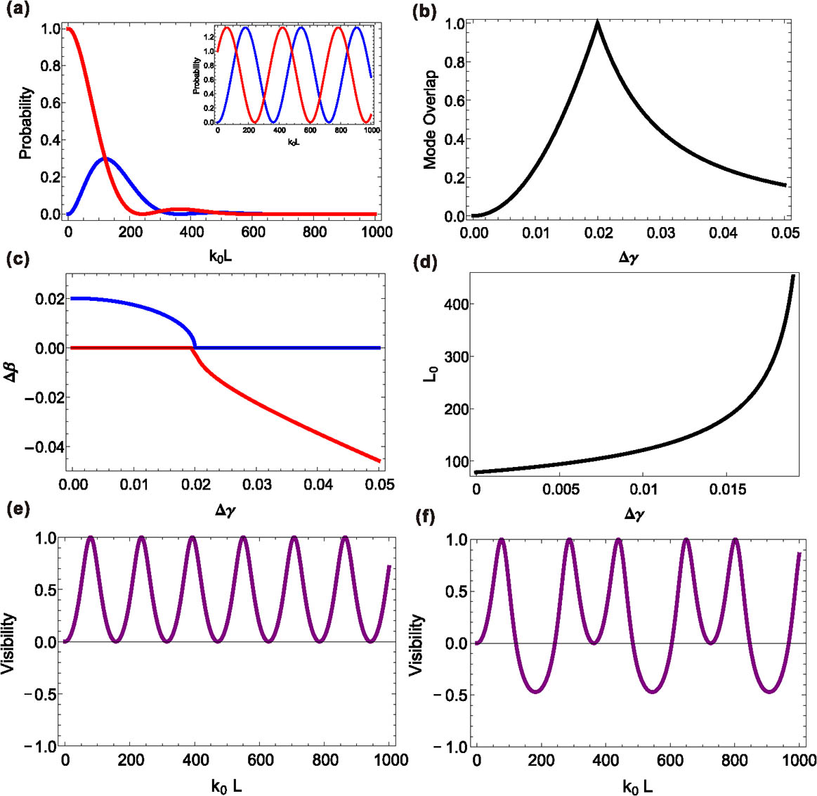
    Fig. 2. (Color online) Two coupled waveguides with an unbalanced linear loss. (a) By injecting a single photon in port 1 in Fig. 1(a), the hopping probability to the outputs are plotted. Blue line: port 1. Red line: port 2. The inset shows the relative intensity eliminating the global damping factor. We set C=0.01k0 and Δγ=0.01k0. (b) The mode overlap |+||2 of the two eigenmodes. (c) The real (blue) and imaginary (red) part of the difference between β+ and β. The cross point is the exceptional point. (d) L0 is the minimum coupling length to achieve 1:1 splitting. (e). Two-photon quantum interference visibility on an ideal BS with C=0.01k0. (f) Two-photon quantum interference visibility on a BS with unbalanced linear loss as a function of the coupling length. C=0.01k0 and Δγ=0.01k0. In all the figures, the units of C and γi are the free-space wave vector k0. We set C=0.01k0 for all the cases.
    (Color online) Single-photon and two-photon interference on a BS with shared CL. (a) Relative probability in two waveguides with single-photon input. (b) The mode overlap |〈+|−〉|2 of the two eigenmodes. (c) The real and imaginary part of β+−β−. (d) The visibility of two-photon quantum interference. The visibility becomes negative and approaches −1 as the coupling region becomes longer. Here we set the damping rate the waveguides γ=0.001k0, C1=0.01k0, and C2=0.0005k0.
    Fig. 3. (Color online) Single-photon and two-photon interference on a BS with shared CL. (a) Relative probability in two waveguides with single-photon input. (b) The mode overlap |+||2 of the two eigenmodes. (c) The real and imaginary part of β+β. (d) The visibility of two-photon quantum interference. The visibility becomes negative and approaches 1 as the coupling region becomes longer. Here we set the damping rate the waveguides γ=0.001k0, C1=0.01k0, and C2=0.0005k0.
    (Color online) Fidelity of quantum gates formed by a BS with shared loss. All quantum gates are decomposed to BSs and phase shifters and we assume the phase shifters are ideal. The fidelity is the minimum value searched through all input quantum states. (a) The gate fidelity for a BS, single-qubit operation, and quantum C-NOT gate. (b) The minimum fidelity for any two-qubit gate and any two-qubit quantum state. In the calculations, C1=0.01k0.
    Fig. 4. (Color online) Fidelity of quantum gates formed by a BS with shared loss. All quantum gates are decomposed to BSs and phase shifters and we assume the phase shifters are ideal. The fidelity is the minimum value searched through all input quantum states. (a) The gate fidelity for a BS, single-qubit operation, and quantum C-NOT gate. (b) The minimum fidelity for any two-qubit gate and any two-qubit quantum state. In the calculations, C1=0.01k0.
    Ming Li, Changling Zou, Guangcan Guo, Xifeng Ren. Effect of unbalanced and common losses in quantum photonic integrated circuits[J]. Chinese Optics Letters, 2017, 15(9): 092701
    Download Citation