
E. F. J. Bacon, M. King, R. Wilson, T. P. Frazer, R. J. Gray, P. McKenna. High order modes of intense second harmonic light produced from a plasma aperture[J]. Matter and Radiation at Extremes, 2022, 7(5): 054401
- Matter and Radiation at Extremes
- Vol. 7, Issue 5, 054401 (2022)
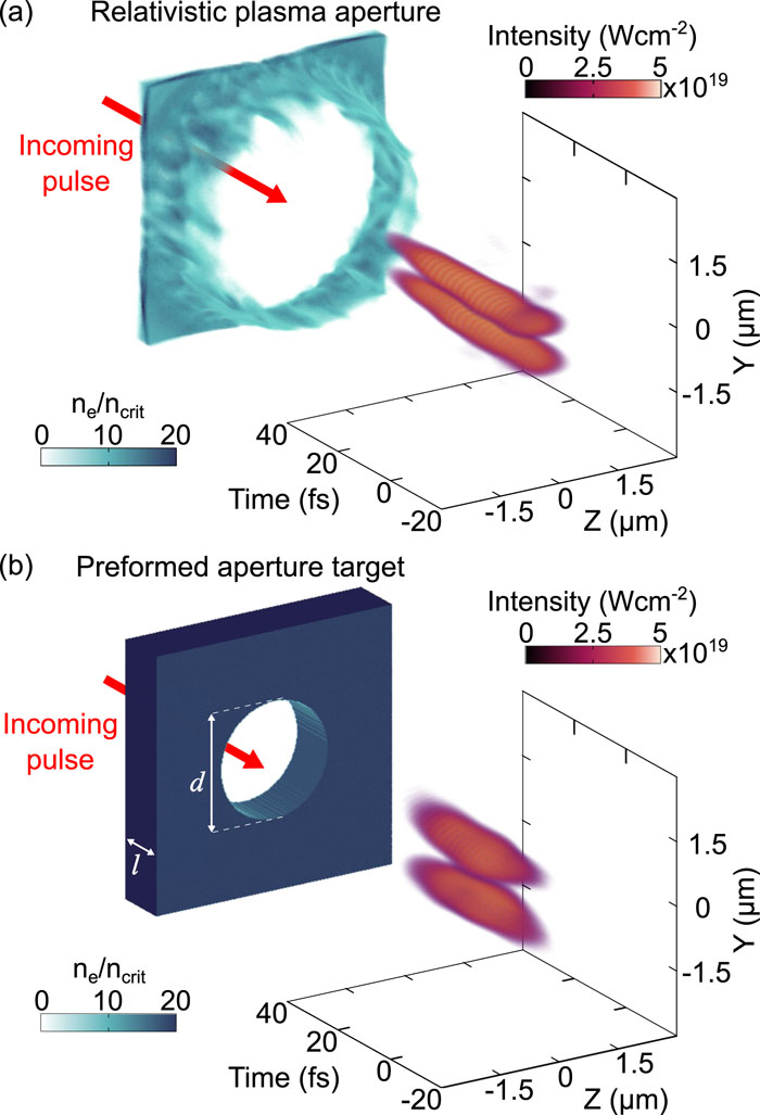
Fig. 1. Example 3D simulation results demonstrating the generation of relativistically intense frequency-doubled light in a higher-order spatial mode (TEM01) driven by intense laser light in a fundamental TEM00 mode: (a) self-generated relativistic plasma aperture in an initially solid-density 10-nm-thick aluminum target; (b) preformed aperture target with thickness l = 2 μ m and aperture diameter d = 3 μ m.
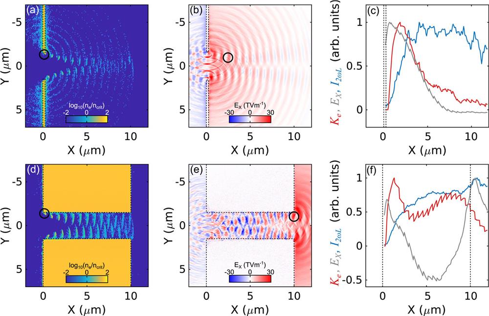
Fig. 2. Top row: 2D simulation results for a target with l = 0.5 μ m and d = 3 μ m: (a) electron density at t = −4.8 fs; (b) longitudinal electric field at t = 2.8 fs; (c) total energy (K e , red) in the electron bunch marked by the black circle in (a) and (b) as it propagates in space, together with the intensity of the 2ω L light generated, averaged 400 nm around the bunch (I 2ωL , blue), and the longitudinal electric field experienced by the bunch (E X , grey) averaged over the same area. Bottom row: (d)–(f) show the corresponding results for l = 10 μ m and d = 3 μ m, with t = 28.8 fs in (e). The dashed black lines indicate the initial positions of the target surfaces and aperture edges.
Fig. 3. 2D simulation results showing the efficiency of 2ω L light generation as a function of target thickness and aperture diameter, after the interaction of a linearly polarized laser pulse with an intensity of: (a) 1021 W cm−2; (b) 1022 W cm−2; and (c) 1023 W cm−2. All of the other laser parameters are fixed. The regions of behavior indicated by the Roman numerals are discussed in the main text.
Fig. 4. Three parameters that vary with both target thickness and aperture diameter, for the interaction with a 1021 W cm−2 laser pulse: (a) magnitude of the longitudinal electric field at the aperture edge; (b) the energy into the aperture; (c) the laser absorption. (d) Conversion efficiency to 2ω L , as defined by Eq. (4) .
Fig. 5. 3D simulation results. (a) 2ω L generation efficiency as a function of d and l . (b) Conversion efficiency as given by Eq. (4) for 3D conditions. (c) and (d) 2ω L generation efficiency as a function of (c) d for l = 6 μ m, and (d) l for d = 3 μ m. 3D linear polarization results are shown in blue and circular polarization results are shown in orange. 2D simulation data are included for comparison (dashed black line) for fixed l = 6 μ m and d = 2 μ m in (c) and (d), respectively. I L = 1021 W cm−2 for all cases.
Fig. 6. Intensity profile of the drive laser light in the XY plane at Z = 0 from 3D simulations, for d = 3 μ m and l = 0.25 μ m, at: (a) t = 16 fs and (b) t = 32 fs. (c) and (d) are the corresponding results for l = 10 μ m. The dashed white lines indicate the initial target profile, and the nominal focused intensity (without plasma) is 1021 W cm−2 in both cases.
Fig. 7. Time-integrated spatial mode structure at 5 μ m from the rear of the target. Top row: linear polarization and d = (a) 1 μ m, (b) 2 μ m, (c) 3 μ m, and (d) 4 μ m, all for l = 6 μ m. Bottom row: corresponding results with circular polarization, with otherwise the same laser and target parameters.
Fig. 8. Time-integrated spatial mode structure at 5 μ m from the rear of the target with d = 4 μ m, for (a) linear polarization and (b) circular polarization. The data are the same as those in Figs. 7(d) and 7(h) , respectively, with fluence plotted on a logarithmic scale to show the higher-order spatial structures present at larger radii.
Fig. 9. (a) Conversion efficiency to 2ω L light as a function of the plasma density within the aperture, for a d = 2 μ m, L = 6 μ m target. (b) Conversion efficiency to 2ω L as a function of the entrance diameter d 1, for a fixed exit diameter d 2 = 2 μ m and l = 6 μ m. (c) Intensity profile of the drive laser light in the XY plane at Z = 0, from 3D simulations, for d 1 = 3 μ m (d 2 = 2 μ m and l = 6 μ m) at t = 23 fs. (d) Same as (c) for d 1 = 8 μ m.


Set citation alerts for the article
Please enter your email address

© Copyright 2018-2021 | Chinese Laser Press. All Rights Reserved 沪ICP备15018463号-20