• Photonics Research
  • Vol. 8, Issue 11, 1734 (2020)
Linpeng Gu1, Liang Fang1, Qingchen Yuan1, Xuetao Gan1、*, Hao Yang1, Xutao Zhang1, Juntao Li2, Hanlin Fang2, Vladislav Khayrudinov3, Harri Lipsanen3, Zhipei Sun3、4, and Jianlin Zhao1、5
Author Affiliations
  • 1Key Laboratory of Space Applied Physics and Chemistry, Ministry of Education, and Shaanxi Key Laboratory of Optical Information Technology, School of Physical Science and Technology, Northwestern Polytechnical University, Xi’an 710129, China
  • 2State Key Laboratory of Optoelectronic Materials & Technologies, School of Physics, Sun Yat-sen University, Guangzhou 510275, China
  • 3Department of Electronics and Nanoengineering, Aalto University, Espoo FI-00076, Finland
  • 4QTF Centre of Excellence, Department of Applied Physics, Aalto University, Espoo FI-00076, Finland
  • 5e-mail: jlzhao@nwpu.edu.cn
  • show less
    DOI: 10.1364/PRJ.397116 Cite this Article Set citation alerts
    Linpeng Gu, Liang Fang, Qingchen Yuan, Xuetao Gan, Hao Yang, Xutao Zhang, Juntao Li, Hanlin Fang, Vladislav Khayrudinov, Harri Lipsanen, Zhipei Sun, Jianlin Zhao. Nanowire-assisted microcavity in a photonic crystal waveguide and the enabled high-efficiency optical frequency conversions[J]. Photonics Research, 2020, 8(11): 1734 Copy Citation Text show less
    (a), (b) Schematic representations of the hybrid structure of an NW and a PPC waveguide; (c) operation principle of the optical frequency upconversion processes (SHG and SFG) with the enhanced light–NW coupling by the NW-induced cavity.
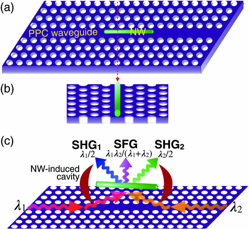
    Fig. 1. (a), (b) Schematic representations of the hybrid structure of an NW and a PPC waveguide; (c) operation principle of the optical frequency upconversion processes (SHG and SFG) with the enhanced light–NW coupling by the NW-induced cavity.
    (a) SEM image of the fabricated device, showing the precise alignment of the NW with the line defect of the PPC waveguide; (b) normalized transmission spectra of the PPC waveguide before and after the integration of the NW, where the asterisks indicate the locations of the resonance modes of the NW-induced PPC cavity; (c) transmission spectra around the resonant mode at 1509 nm when the input laser has different powers of 5 mW (blue dots), 10 mW (red dots), and 15 mW (green dots). Black lines are fitting curves with Fano-type line shapes.
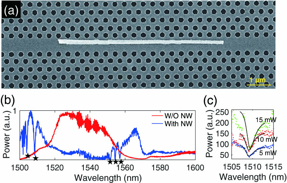
    Fig. 2. (a) SEM image of the fabricated device, showing the precise alignment of the NW with the line defect of the PPC waveguide; (b) normalized transmission spectra of the PPC waveguide before and after the integration of the NW, where the asterisks indicate the locations of the resonance modes of the NW-induced PPC cavity; (c) transmission spectra around the resonant mode at 1509 nm when the input laser has different powers of 5 mW (blue dots), 10 mW (red dots), and 15 mW (green dots). Black lines are fitting curves with Fano-type line shapes.
    (a) Band diagram of the odd (upper) and even (lower) guiding modes in the PPC waveguides with (red square) and without (black square) the NW; (b) mode distributions of the even and odd resonant modes at different orders calculated from an NW-integrated PPC waveguide. The arrows indicate that the resonant modes arise from the localizations of the corresponding odd and even transmission bands of the NW-integrated PPC waveguide.
    Fig. 3. (a) Band diagram of the odd (upper) and even (lower) guiding modes in the PPC waveguides with (red square) and without (black square) the NW; (b) mode distributions of the even and odd resonant modes at different orders calculated from an NW-integrated PPC waveguide. The arrows indicate that the resonant modes arise from the localizations of the corresponding odd and even transmission bands of the NW-integrated PPC waveguide.
    (a) Spectrum of SHG from the vertical scattering signal of the NW–PPC waveguide with the pump of a 1509.0 nm laser; (b) log-log plot of the SHG powers and pump powers fitted by a line with a slope of 2.08; (c) measured SHG powers when the pump laser is scanned over the wavelength range of 1500–1600 nm, where the linear transmission spectrum of the pump laser is shown as well for cross-reference; (d) polarization property of the scattered SHG signal, where the polar angle is defined with respect to the long axis of the NW.
    Fig. 4. (a) Spectrum of SHG from the vertical scattering signal of the NW–PPC waveguide with the pump of a 1509.0 nm laser; (b) log-log plot of the SHG powers and pump powers fitted by a line with a slope of 2.08; (c) measured SHG powers when the pump laser is scanned over the wavelength range of 1500–1600 nm, where the linear transmission spectrum of the pump laser is shown as well for cross-reference; (d) polarization property of the scattered SHG signal, where the polar angle is defined with respect to the long axis of the NW.
    (a) Spectrum of the scattered frequency upconversion signals pumped by two on-resonance lasers at 1509.0 and 1554.8 nm, showing SHG and SFG signals; (b) log-log plot of the SFG powers and pump powers fitted by a line with a slope of 2.03; (c) measured SFG powers with one pump laser fixed at 1509.0 nm and the other pump laser scanned across 1540–1570 nm, where the linear transmission spectrum of the pump laser is shown as well for cross-reference; (d) polarization properties of SHG and SFG signals with respect to the long axis of the NW.
    Fig. 5. (a) Spectrum of the scattered frequency upconversion signals pumped by two on-resonance lasers at 1509.0 and 1554.8 nm, showing SHG and SFG signals; (b) log-log plot of the SFG powers and pump powers fitted by a line with a slope of 2.03; (c) measured SFG powers with one pump laser fixed at 1509.0 nm and the other pump laser scanned across 1540–1570 nm, where the linear transmission spectrum of the pump laser is shown as well for cross-reference; (d) polarization properties of SHG and SFG signals with respect to the long axis of the NW.
    Linpeng Gu, Liang Fang, Qingchen Yuan, Xuetao Gan, Hao Yang, Xutao Zhang, Juntao Li, Hanlin Fang, Vladislav Khayrudinov, Harri Lipsanen, Zhipei Sun, Jianlin Zhao. Nanowire-assisted microcavity in a photonic crystal waveguide and the enabled high-efficiency optical frequency conversions[J]. Photonics Research, 2020, 8(11): 1734
    Download Citation