• Photonics Research
  • Vol. 11, Issue 1, 121 (2023)
Xinglin Wang1、2, Wenxiang Yan1, Yuan Gao1, Zheng Yuan1, Zhi-Cheng Ren1, Xi-Lin Wang1, Jianping Ding1、3、4、*, and Hui-Tian Wang1
Author Affiliations
  • 1National Laboratory of Solid Microstructures and School of Physics, Nanjing University, Nanjing 210093, China
  • 2Department of Applied Mathematics and Physics, Anhui Polytechnic University, Wuhu 241000, China
  • 3Collaborative Innovation Center of Advanced Microstructures, Nanjing University, Nanjing 210093, China
  • 4Collaborative Innovation Center of Solid-State Lighting and Energy-Saving Electronics, Nanjing University, Nanjing 210093, China
  • show less
    DOI: 10.1364/PRJ.470931 Cite this Article Set citation alerts
    Xinglin Wang, Wenxiang Yan, Yuan Gao, Zheng Yuan, Zhi-Cheng Ren, Xi-Lin Wang, Jianping Ding, Hui-Tian Wang. Manipulating propagation and evolution of polarization singularities in composite Bessel-like fields[J]. Photonics Research, 2023, 11(1): 121 Copy Citation Text show less
    Experiment setup used to generate composite Bessel-like VOFs and manipulate propagation and evolution of the embedded PSs. P, polarizer; SLM, spatial light modulator; BS, beam splitter; L1–L3, lenses; A-QWP, assembled quarter-wave plate; G, Ronchi grating.
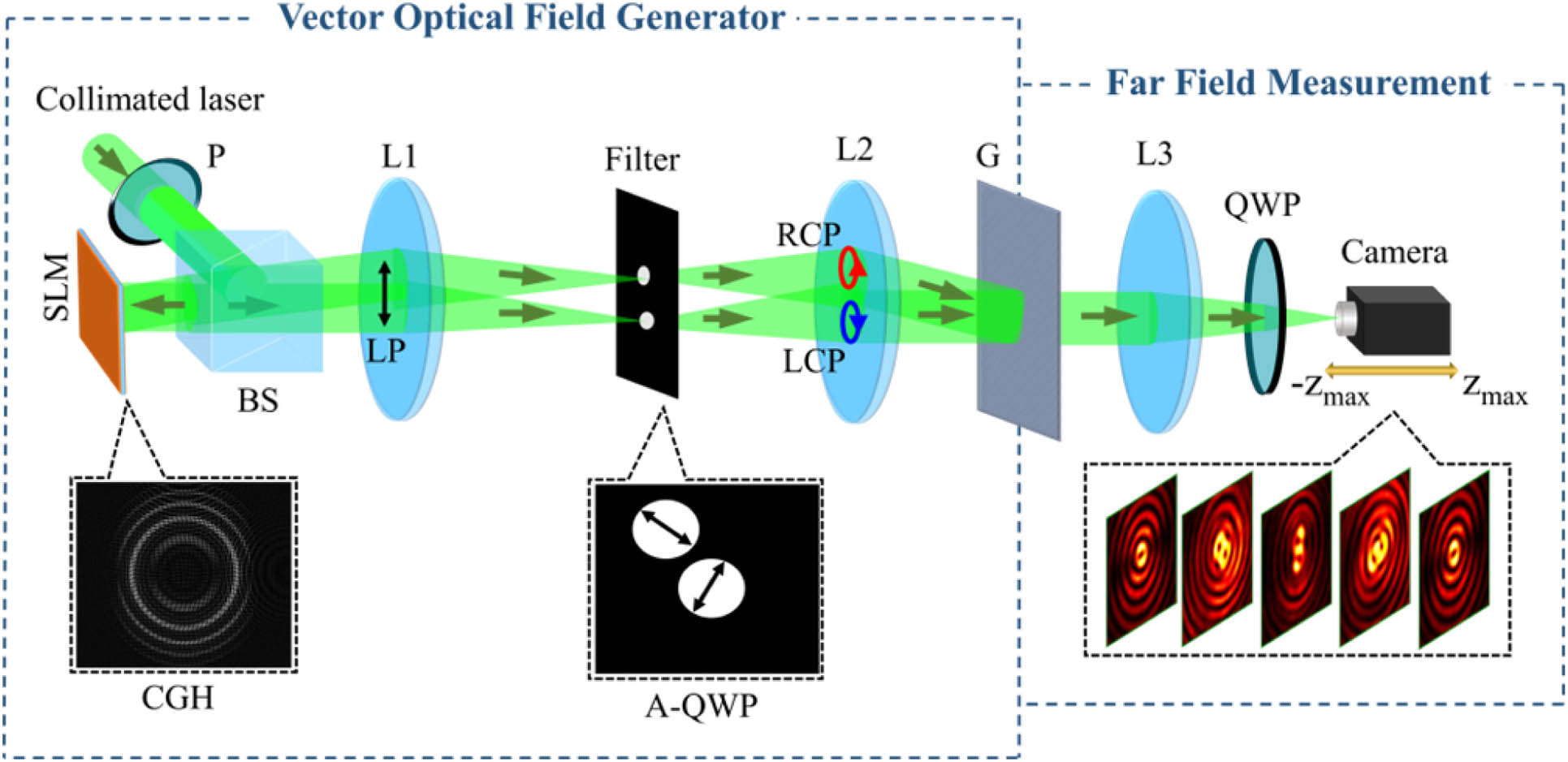
    Fig. 1. Experiment setup used to generate composite Bessel-like VOFs and manipulate propagation and evolution of the embedded PSs. P, polarizer; SLM, spatial light modulator; BS, beam splitter; L1–L3, lenses; A-QWP, assembled quarter-wave plate; G, Ronchi grating.
    Numerical and experimental demonstrations of the manipulated propagation trajectories of PSs in form of braiding. (a) Simulated side-view propagation of the composite Bessel-like beam and (b) transverse beam patterns at three different positions. (c) The spiral propagation trajectories of the C-points (i.e., C-lines, depicted by continuous lines) are accompanied by a top-view image at the bottom, and the polarization distribution in the Fourier plane is indicated as an inset to suggest the initial field with lemon–star topological configuration, where the red and blue colors denote RH and LH polarization states. (d) and (e) Measured transverse beam patterns and Stokes phases ϕ12 at different positions, where the white and black circles represent the Stokes vortices, corresponding to positive and negative C-points marked by dots on the C-lines in (c), respectively.
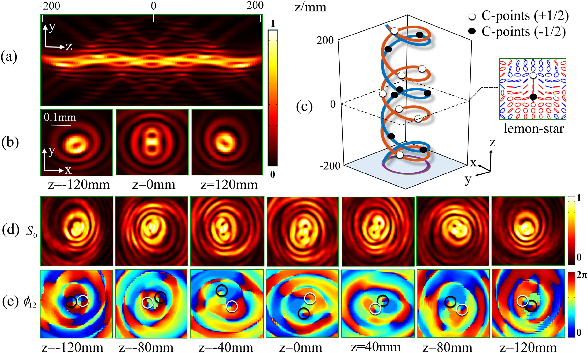
    Fig. 2. Numerical and experimental demonstrations of the manipulated propagation trajectories of PSs in form of braiding. (a) Simulated side-view propagation of the composite Bessel-like beam and (b) transverse beam patterns at three different positions. (c) The spiral propagation trajectories of the C-points (i.e., C-lines, depicted by continuous lines) are accompanied by a top-view image at the bottom, and the polarization distribution in the Fourier plane is indicated as an inset to suggest the initial field with lemon–star topological configuration, where the red and blue colors denote RH and LH polarization states. (d) and (e) Measured transverse beam patterns and Stokes phases ϕ12 at different positions, where the white and black circles represent the Stokes vortices, corresponding to positive and negative C-points marked by dots on the C-lines in (c), respectively.
    Customization of the hexapetalous PSs topological configuration. (a) Simulated side-view propagation of the composite Bessel-like beam and (b) transverse beam patterns at three different positions. (c) Dislocated trefoil propagation trajectories of the C-points and their top-view images, together with an inset depicting the polarization distribution in the Fourier plane, where the red and blue colors denote RH and LH polarization states. (d) and (e) Measured transverse beam patterns and Stokes phases ϕ12 at different positions, where the Stokes vortices are marked by white and black circles, corresponding to positive and negative C-points marked by dots on the C-lines in (c), respectively.
    Fig. 3. Customization of the hexapetalous PSs topological configuration. (a) Simulated side-view propagation of the composite Bessel-like beam and (b) transverse beam patterns at three different positions. (c) Dislocated trefoil propagation trajectories of the C-points and their top-view images, together with an inset depicting the polarization distribution in the Fourier plane, where the red and blue colors denote RH and LH polarization states. (d) and (e) Measured transverse beam patterns and Stokes phases ϕ12 at different positions, where the Stokes vortices are marked by white and black circles, corresponding to positive and negative C-points marked by dots on the C-lines in (c), respectively.
    Numerical and experimental demonstrations of the manipulated evolution of PSs in 3D space. (a) Simulated side-view propagation of the composite Bessel-like beam and (b) transverse beam patterns at three different positions. (c) The evolution trajectories (continuous lines) are accompanied by three slices of Stokes phase and polarization distributions at the same three positions as those in (b), where the red and blue colors describe RH and LH polarization states, white and black dots denote positive and negative C-points, and gray dots represent the annihilation points of the C-points, respectively. (d) and (e) Measured transverse beam patterns and Stokes phases at different positions, where the white and black circles denote the Stokes vortices corresponding to the positive and negative C-points marked by dots on the lines in (c), and the dotted circles denote the annihilation points.
    Fig. 4. Numerical and experimental demonstrations of the manipulated evolution of PSs in 3D space. (a) Simulated side-view propagation of the composite Bessel-like beam and (b) transverse beam patterns at three different positions. (c) The evolution trajectories (continuous lines) are accompanied by three slices of Stokes phase and polarization distributions at the same three positions as those in (b), where the red and blue colors describe RH and LH polarization states, white and black dots denote positive and negative C-points, and gray dots represent the annihilation points of the C-points, respectively. (d) and (e) Measured transverse beam patterns and Stokes phases at different positions, where the white and black circles denote the Stokes vortices corresponding to the positive and negative C-points marked by dots on the lines in (c), and the dotted circles denote the annihilation points.
    Piecewise design of the z-axis evolution of PS topological morphology. (a) Simulated side-view propagation of the composite Bessel-like beam and (b) transverse beam patterns at three typical positions. (c) Evolution trajectories (continuous lines) with three slices of Stokes phase and polarization distributions at six characteristic positions, where the red and blue colors describe RH and LH polarization states, white and black dots denote positive and negative C-points, green and yellow dots denote positive and negative V-points, and gray dots represent the annihilation points of PSs, respectively. (d) and (e) Measured transverse beam patterns and Stokes phases at different positions. In (e), the white, black, green, and yellow circles represent the Stokes vortices corresponding to the positive C-points, negative C-points, positive V-point, and negative V-point, respectively, while the dotted circles denote the annihilation points.
    Fig. 5. Piecewise design of the z-axis evolution of PS topological morphology. (a) Simulated side-view propagation of the composite Bessel-like beam and (b) transverse beam patterns at three typical positions. (c) Evolution trajectories (continuous lines) with three slices of Stokes phase and polarization distributions at six characteristic positions, where the red and blue colors describe RH and LH polarization states, white and black dots denote positive and negative C-points, green and yellow dots denote positive and negative V-points, and gray dots represent the annihilation points of PSs, respectively. (d) and (e) Measured transverse beam patterns and Stokes phases at different positions. In (e), the white, black, green, and yellow circles represent the Stokes vortices corresponding to the positive C-points, negative C-points, positive V-point, and negative V-point, respectively, while the dotted circles denote the annihilation points.
    Xinglin Wang, Wenxiang Yan, Yuan Gao, Zheng Yuan, Zhi-Cheng Ren, Xi-Lin Wang, Jianping Ding, Hui-Tian Wang. Manipulating propagation and evolution of polarization singularities in composite Bessel-like fields[J]. Photonics Research, 2023, 11(1): 121
    Download Citation