
Ping Xue, Hai He, Hongmin Wang. Error Correction Algorithm for Optical Measurement System Based on Radial Basis Function Network[J]. Acta Optica Sinica, 2020, 40(2): 0212004
- Acta Optica Sinica
- Vol. 40, Issue 2, 0212004 (2020)
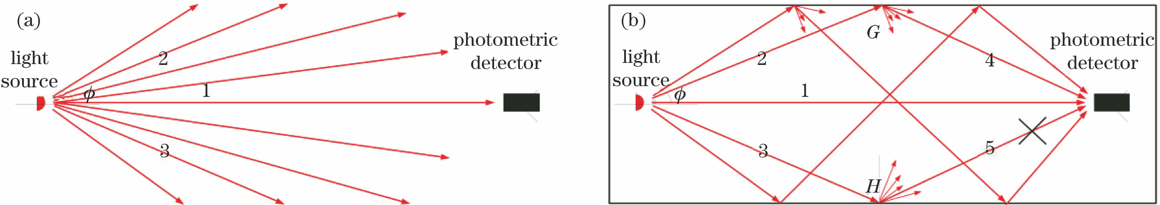
Fig. 1. Tracing analysis of stray light effect in photometric measurement system. (a) Optical ray in ideal photometric measurement system; (b) optical ray in general photometric measurement system
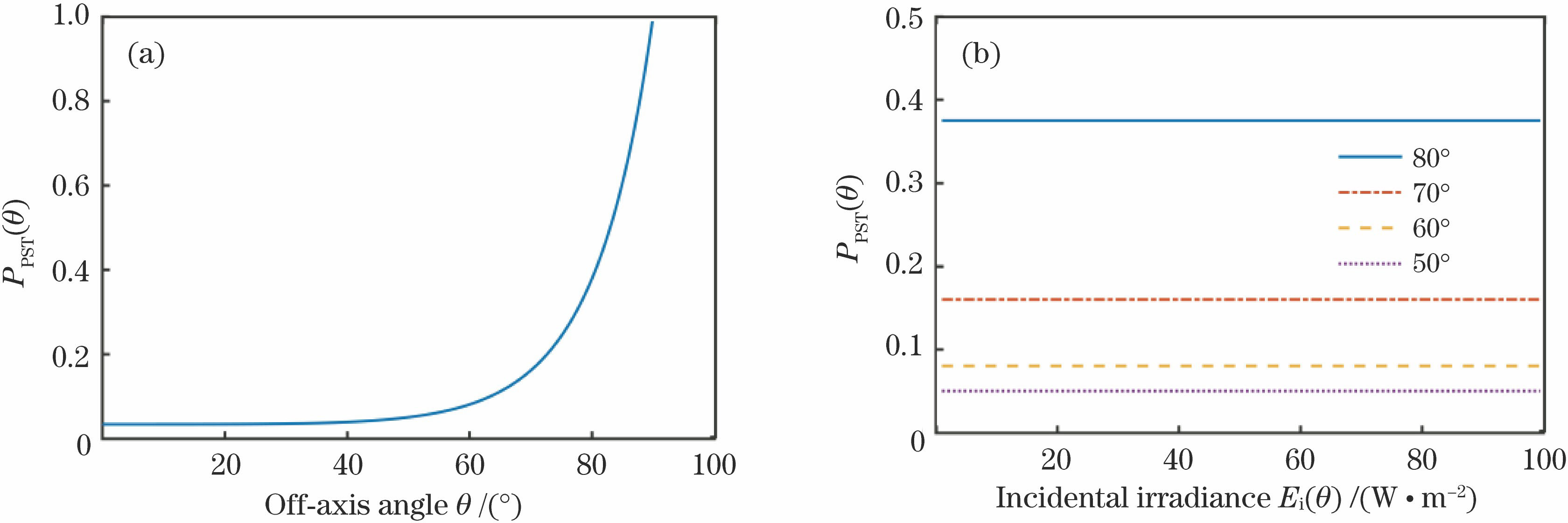
Fig. 2. Varying curves of PST values under different conditions. (a) PST value as a function of off-axis angle; (b) PST value as a function of irradiance
Fig. 3. Principle of three-dimensional ray tracing analysis for photometric measurement system
Fig. 4. RBF network model for error correction of photometric measurement
Fig. 5. Improved error correction model for RBF network
Fig. 6. Comparison of RBF training processes before and after improvement
Fig. 7. Aperture structure of inner wall of optical darkroom
Fig. 8. Simulation model of distributed photometric measurement platform. (a) Infinite space; (b) general photometric measurement system; (c) photometric measurement system with triple aperture denoising structure
Fig. 9. Comparison of theoretical and measured values of luminous intensity
Fig. 10. Analysis charts of correction results of RBF network. (a) Outputs of photometric data before and after correction; (b) distributions of errors before and after correction
|
Table 1. Basic information of light source measurement environment

Set citation alerts for the article
Please enter your email address
© Copyright 2018-2021 | Chinese Laser Press. All Rights Reserved 沪ICP备15018463号-20