
Tiegen Liu, Xun Yu, Shuang Wang, Junfeng Jiang, Kun Liu. Fiber-Optic Fabry-Perot Sensing Technology in High-Temperature Environments: An Review[J]. Laser & Optoelectronics Progress, 2021, 58(13): 1306002
- Laser & Optoelectronics Progress
- Vol. 58, Issue 13, 1306002 (2021)
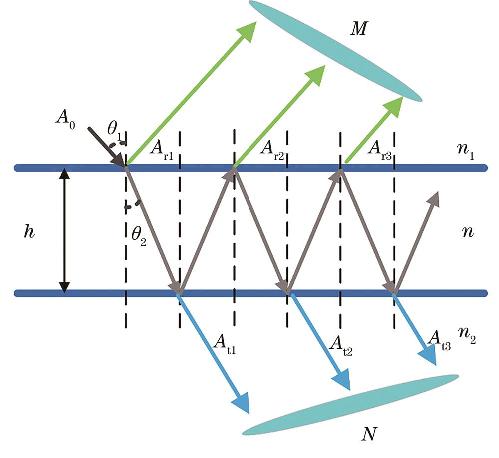
Fig. 1. Multi-beam interference model of Fabry-Perot microcavity
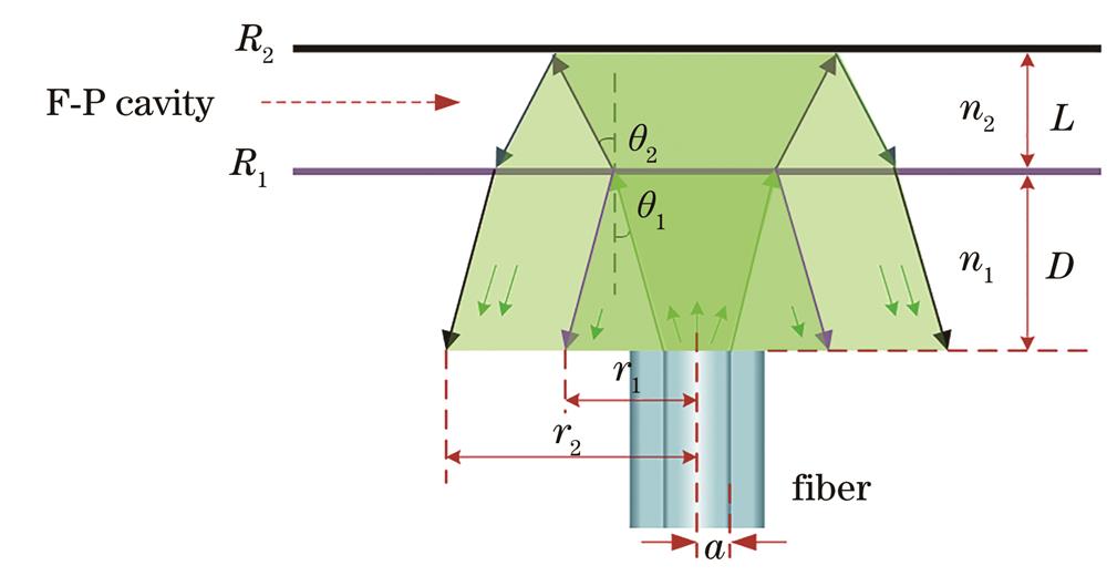
Fig. 2. Reflected beam and fiber coupling model of Fabry-Perot cavity
Fig. 3. Configuration of three spliced air gap-based Fabry-Perot sensor[38]
Fig. 4. Experiment results of all-sapphire single-crystal fiber Fabry-Perot sensor fabricated by femtosecond laser micro-machining and CO2 laser welding[40]. (a)(b) Microscopic and scanning electron microscopic image of the bottom surface of the pit before the CO2 laser surface smoothing; (c)(d) corresponding microscopic and scanning electron microscopic image after the CO2 laser surface smoothing; (e) image of the laser-welded sensor head (the inset shows the image of at the welding plane); (f) image of the fabricated sensor head
Fig. 5. Schematic diagrams of thin-film fiber-optic Fabry-Perot microcavity sensor and sensing system[41]
Fig. 6. Schematic diagram of 45° inclined fiber diaphragm sensor head[46]. (a) Sensing optical path diagram of 45°inclined optical fiber diaphragm sensor;(b) axial diagram of 45° inclined fiber diaphragm sensor
Fig. 7. Actual picture of the flame experiment of the patch type sapphire fiber Fabry-Perot sensor
Fig. 8. Parallel dual-waveguide Fabry-Perot high temperature sensor[50]. (a) Structure diagram of the sensor; (b) schematic diagram of the sensing optical path
Fig. 9. Schematic diagram of laser micromachined composite Fabry-Perot sensor[51]
Fig. 10. Micrograph of the composite fiber-optic Fabry-Perot sensor made by the etching method combined with the optical fiber splicing technology[52]
Fig. 11. Special fiber splicing composite Fabry-Perot sensor[53]. (a) Schematic diagram; (b) micrograph
Fig. 12. Structure and sensing characteristics of all-silicon dual-cavity optical fiber pressure sensor[55]. (a) Schematic diagram of the all-silicon-based dual-cavity fiber-optic pressure sensor structure (all the components are high-temperature resistant materials); (b) interference model of the dual-cavity structure with three reflective mirrors; (c) simulation of reflected spectra IR(λ) (simulation parameters: n1=1, n2=3.47, L1=60 μm, L2=300 μm, I0 is the light intensity of a broadband light source with a central wavelength of 1550 nm)
Fig. 13. Schematic diagram of structure and sensing principle of pure sapphire crystal bonded F-P sensor[56]. (a) Schematic of the sensor structure; (b) sensor sensing principle and spectrum curve diagram

Set citation alerts for the article
Please enter your email address
© Copyright 2018-2021 | Chinese Laser Press. All Rights Reserved 沪ICP备15018463号-20