
Chenghang Li, Junpeng Xue, Wei Lang, Qican Zhang. Method for Interpolation of Missing Point Cloud Based on Phase Mapping in Binocular Vision[J]. Acta Optica Sinica, 2020, 40(1): 0111019
- Acta Optica Sinica
- Vol. 40, Issue 1, 0111019 (2020)
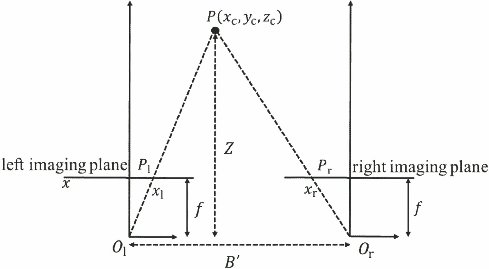
Fig. 1. Imaging model of binocular stereo vision
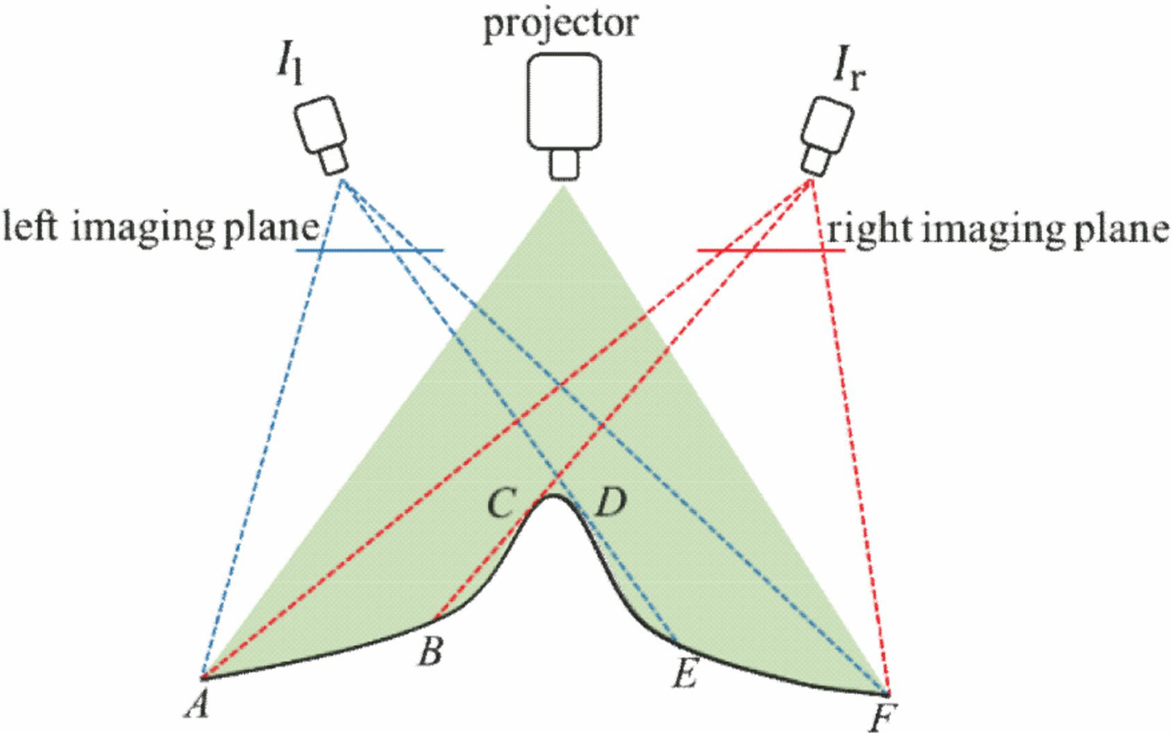
Fig. 2. Occlusion diagram of binocular vision measurement system
Fig. 3. Display of binocular vision system measurement data. (a) Distorted fringe image of left camera; (b) distorted fringe image of right camera; (c) reconstructed result of facial mask
Fig. 4. Calibration diagram of implicit phase-height mapping relationship
Fig. 5. Analysis on calibration parameter of implicit phase-height mapping relationship. (a) a(u,v); (b) b(u,v); (c) c(u,v)
Fig. 6. Fringe patterns taken by camera and fringe spectrum. (a) Vertically distributed fringe pattern; (b) inclined fringe pattern; (c) Fourier spectrum distribution of fringe pattern
Fig. 7. Diagram of point cloud missing area
Fig. 8. Flow chart of proposed method
Fig. 9. Experimental setup
Fig. 10. Measurement results of standard sample with two balls. (a) Remove part of complete point cloud data of standard sample as holes to be interpolated; (b) interpolated result by proposed method
Fig. 11. Reconstructed result of facial mask. (a) Reconstructed result with local point cloud data missing on both sides of nose and some point cloud data artificially deducted in upper lip; (b) interpolated result of proposed method; (c) interpolated point cloud data in left nasal alar; (d) interpolated point cloud data in right nasal alar; (e) interpolated point cloud data in upper lip; (f) difference distribution between interpolated result and measured result of point cloud deducted area in upper lip
Fig. 12. Interpolated results of facial mask by Geomagic. (a) Reconstructed result by Geomagic with local point cloud data missing on both sides of nose and some point cloud data artificially deducted in upper lip; (b) interpolated point cloud data by Geomagic in left nasal alar; (c) interpolated point cloud data by Geomagic in right nasal alar; (d) interpolated point cloud data by Geomagic in upper lip; (e) comparison of interpolated results of proposed method and Geomagic in upper lip; (f) difference d
Fig. 13. Experiment results of gourd model. (a) Binocular reconstructed result with point cloud absence in both ends and middle part; (b) interpolated result of proposed method; (c) interpolated point cloud data in left end; (d) interpolated point cloud data in right end
| |||||||||||||||||||||||||||||||||||||||||||||||||||||||||||||||||||||||||||||||||||||||||||||||||||||||||||||||||||||||||||||||||||||||||||||||||||||||||||||||||||||||||||||||||||||||||||||||||||||||||||||||||||||||||||
Table 1. Accuracy evaluation of binocular vision system and proposed methodmm

Set citation alerts for the article
Please enter your email address
© Copyright 2018-2021 | Chinese Laser Press. All Rights Reserved 沪ICP备15018463号-20