• Photonics Research
  • Vol. 9, Issue 4, 583 (2021)
Chong Zhang1、2, Jingpei Hu1、2、4、*, Yangeng Dong1、2, Aijun Zeng1、2、5、*, Huijie Huang1、2, and Chinhua Wang3
Author Affiliations
  • 1Laboratory of Information Optics and Optoelectronic Technology, Shanghai Institute of Optics and Fine Mechanics, Chinese Academy of Sciences, Shanghai 201800, China
  • 2Center of Materials Science and Optoelectronics Engineering, University of Chinese Academy of Sciences, Beijing 100049, China
  • 3Key Laboratory of Advanced Optical Manufacturing Technologies of Jiangsu Province and Key Laboratory of Modern Optical Technologies of Ministry of Education, Soochow University, Suzhou 215006, China
  • 4e-mail: hujingpei@siom.ac.cn
  • 5e-mail: aijunzeng@siom.ac.cn
  • show less
    DOI: 10.1364/PRJ.415342 Cite this Article Set citation alerts
    Chong Zhang, Jingpei Hu, Yangeng Dong, Aijun Zeng, Huijie Huang, Chinhua Wang. High efficiency all-dielectric pixelated metasurface for near-infrared full-Stokes polarization detection[J]. Photonics Research, 2021, 9(4): 583 Copy Citation Text show less
    Schematic of setup for near-infrared full-Stokes detection. (a) Polarization measurement device with the metasurface and the CCD array. Each pixel of the metasurface is composed of four different polarization filters. (b) Three-dimensional schematic of the pixel unit with four spatially distributed polarization filters. The colors are used only for distinguishment of the image and bear no wavelength information. (F0, F1, F2) and F3 represent LP and CP filters, respectively. (c) CP filter with the Z-shaped pattern, which transmits right-circularly polarized light (green) and blocks left-circularly polarized light (blue). (d) LP filter consists of the nanowire grid grating, which transmits (blocks) TM (TE) polarized light with the electric field vector perpendicular (parallel) to the grating grooves.
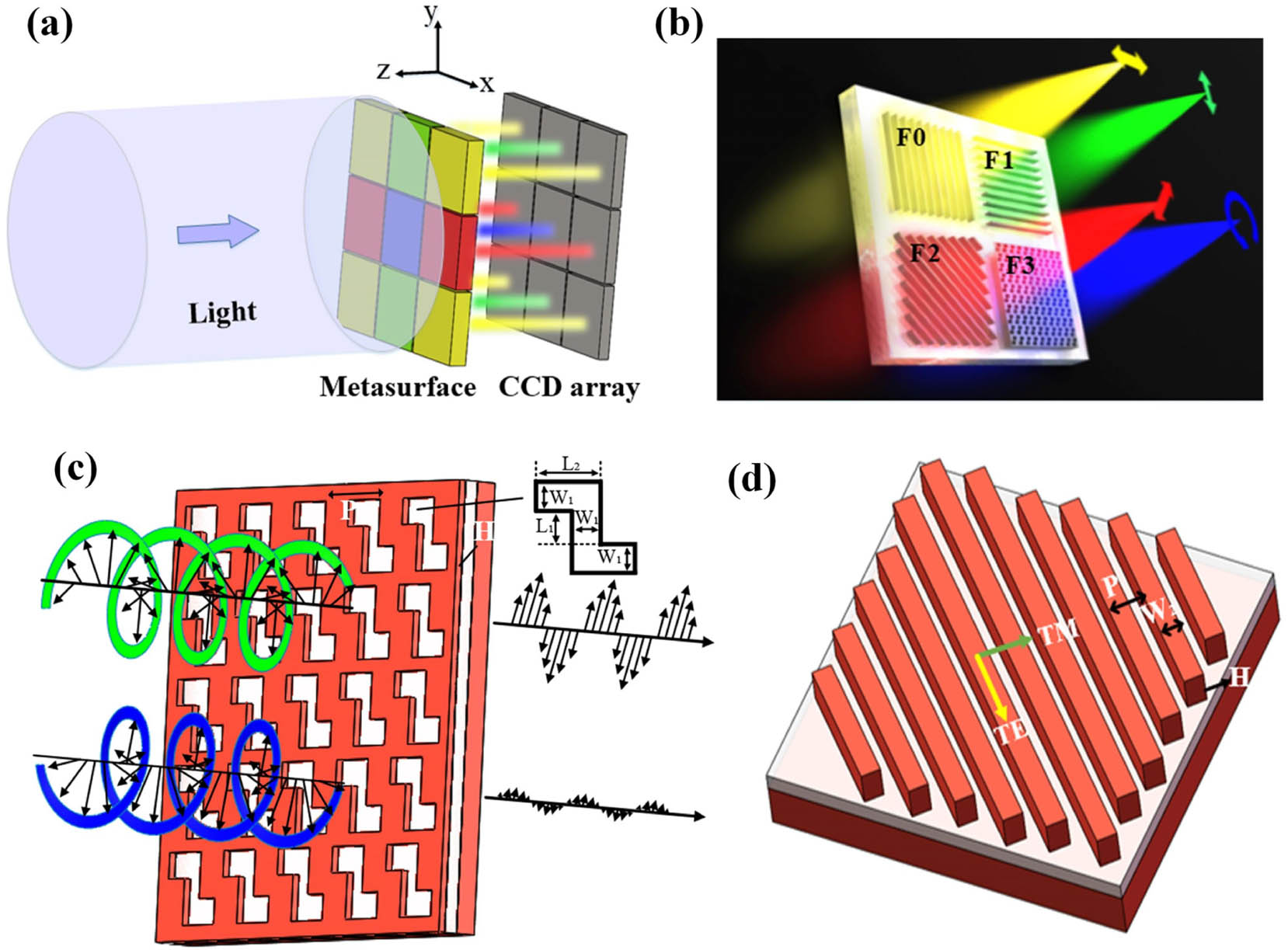
    Fig. 1. Schematic of setup for near-infrared full-Stokes detection. (a) Polarization measurement device with the metasurface and the CCD array. Each pixel of the metasurface is composed of four different polarization filters. (b) Three-dimensional schematic of the pixel unit with four spatially distributed polarization filters. The colors are used only for distinguishment of the image and bear no wavelength information. (F0, F1, F2) and F3 represent LP and CP filters, respectively. (c) CP filter with the Z-shaped pattern, which transmits right-circularly polarized light (green) and blocks left-circularly polarized light (blue). (d) LP filter consists of the nanowire grid grating, which transmits (blocks) TM (TE) polarized light with the electric field vector perpendicular (parallel) to the grating grooves.
    Simulation performances of the CP filters. (a) Transmission spectra of the CP filter for RCP (black) and LCP (red) light as the parameters of the Z-shaped pattern are as follows: W1=0.32 μm, L1=0.22 μm, L2=0.48 μm, H=0.22 μm, and P=0.98 μm. (b) The corresponding CD of the CP filter. The electric field cross section diagram at H=0.2 μm for (c) RCP light and (d) LCP light at the wavelength of 1.6 μm.
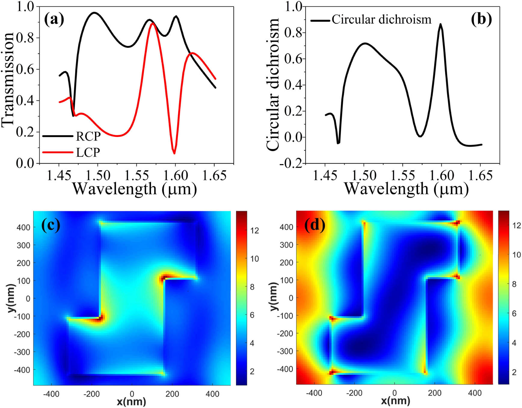
    Fig. 2. Simulation performances of the CP filters. (a) Transmission spectra of the CP filter for RCP (black) and LCP (red) light as the parameters of the Z-shaped pattern are as follows: W1=0.32  μm, L1=0.22  μm, L2=0.48  μm, H=0.22  μm, and P=0.98  μm. (b) The corresponding CD of the CP filter. The electric field cross section diagram at H=0.2  μm for (c) RCP light and (d) LCP light at the wavelength of 1.6 μm.
    Simulation performances of the LP filters. (a) Transmission spectra of the LP filter for TM (black) and TE (red) light as the parameters of nanowire gratings are as follows: W2=0.32 μm, H=0.22 μm, and P=0.98 μm. (b) The corresponding extinction ratio of the LP filter. The electric field cross section diagram of the dielectric grating filter for (c) TM light and (d) TE light at the response wavelength of 1.54 μm.
    Fig. 3. Simulation performances of the LP filters. (a) Transmission spectra of the LP filter for TM (black) and TE (red) light as the parameters of nanowire gratings are as follows: W2=0.32  μm, H=0.22  μm, and P=0.98  μm. (b) The corresponding extinction ratio of the LP filter. The electric field cross section diagram of the dielectric grating filter for (c) TM light and (d) TE light at the response wavelength of 1.54 μm.
    Scanning electron microscope (SEM) image. (a) SEM image of the fabricated devices. (b) Enlarged SEM image of the LP filters with nanowire gratings. (c) Enlarged SEM image of the CP filters with the Z-shaped pattern.
    Fig. 4. Scanning electron microscope (SEM) image. (a) SEM image of the fabricated devices. (b) Enlarged SEM image of the LP filters with nanowire gratings. (c) Enlarged SEM image of the CP filters with the Z-shaped pattern.
    Experimental setup and measurement results of the LP and CP filters. (a) Schematic of the measurement setup for CP filter characterization. (b) Transmission spectra of RCP and LCP light and (c) corresponding CD of the CP filter. (d) Transmission spectra of TM and TE polarized light and (e) corresponding extinction ratio of the LP filter.
    Fig. 5. Experimental setup and measurement results of the LP and CP filters. (a) Schematic of the measurement setup for CP filter characterization. (b) Transmission spectra of RCP and LCP light and (c) corresponding CD of the CP filter. (d) Transmission spectra of TM and TE polarized light and (e) corresponding extinction ratio of the LP filter.
    Chong Zhang, Jingpei Hu, Yangeng Dong, Aijun Zeng, Huijie Huang, Chinhua Wang. High efficiency all-dielectric pixelated metasurface for near-infrared full-Stokes polarization detection[J]. Photonics Research, 2021, 9(4): 583
    Download Citation