• Chinese Optics Letters
  • Vol. 19, Issue 5, 051901 (2021)
Shangqing Li1、2, Jinglong Ma1, Xiaojun Wu3、*, Baolong Zhang1、2, Chen Ouyang1、2, Tianze Wang1、2, Dan Wang1、2, Xuan Wang1, and Yutong Li1、2、4、5、**
Author Affiliations
  • 1Beijing National Laboratory for Condensed Matter Physics, Institute of Physics, Chinese Academy of Sciences, Beijing 100190, China
  • 2School of Physical Sciences, University of Chinese Academy of Sciences, Beijing 100049, China
  • 3School of Electronic and Information Engineering, Beihang University, Beijing 100191, China
  • 4Songshan Lake Materials Laboratory, Dongguan 523808, China
  • 5CAS Center for Excellence in Ultra-intense Laser Science, Shanghai 201800, China
  • show less
    DOI: 10.3788/COL202119.051901 Cite this Article Set citation alerts
    Shangqing Li, Jinglong Ma, Xiaojun Wu, Baolong Zhang, Chen Ouyang, Tianze Wang, Dan Wang, Xuan Wang, Yutong Li. Double-slit diffraction of terahertz wave generated by tilted-pulse-front pumping[J]. Chinese Optics Letters, 2021, 19(5): 051901 Copy Citation Text show less
    Terahertz diffraction diagnostic system and the matched intense terahertz source. (a) Schematic diagram of the experimental setup for the terahertz diffraction method. (b) Typical terahertz temporal waveform and (c) its corresponding spectrum. (d) Focused terahertz beam profile recorded by a terahertz camera without the double slit when L=177.8 mm.
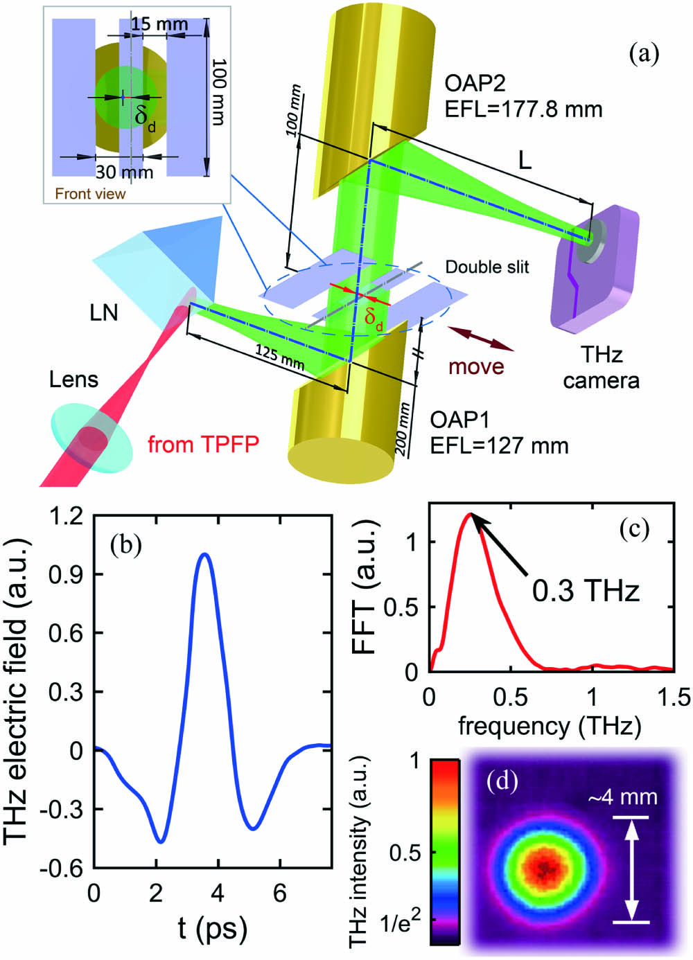
    Fig. 1. Terahertz diffraction diagnostic system and the matched intense terahertz source. (a) Schematic diagram of the experimental setup for the terahertz diffraction method. (b) Typical terahertz temporal waveform and (c) its corresponding spectrum. (d) Focused terahertz beam profile recorded by a terahertz camera without the double slit when L=177.8mm.
    Experimental and simulation results illustrating the relevance between terahertz diffraction patterns received by the terahertz camera and double-slit position. (a)–(c) Meridional diffraction fields and the corresponding diffraction patterns for different double-slit positions δd=−5, 0, and 8 mm, respectively. (d) Peak intensity position δp in terahertz diffraction patterns as a function of double-slit position δd.
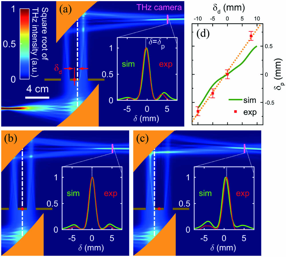
    Fig. 2. Experimental and simulation results illustrating the relevance between terahertz diffraction patterns received by the terahertz camera and double-slit position. (a)–(c) Meridional diffraction fields and the corresponding diffraction patterns for different double-slit positions δd=5, 0, and 8 mm, respectively. (d) Peak intensity position δp in terahertz diffraction patterns as a function of double-slit position δd.
    Diffraction diagnostics for monitoring the moving of the terahertz beam. (a) Experimental setup to diagnose tiny variations of the terahertz beam direction and position. (b) The pump shrinks and tilted terahertz wave is emitted when closing the iris. The green circle indicates the outline of the terahertz beam waist on the terahertz emitting surface of the LN crystal. The green Gaussian curve marked by the dashed-line arrow implies the intensity distribution of the terahertz beam when the iris is fully open. (c) Superior limit of the calculated terahertz beam profile on its emitting surface for different iris sizes. Dark purple line corresponds to Ø=40 mm, blue 20 mm, and yellow 15 mm, respectively. (d) Experimental diffraction patterns received by the terahertz camera. (e) Extracted experimental movement of the terahertz beam compared with the theoretical calculations.
    Fig. 3. Diffraction diagnostics for monitoring the moving of the terahertz beam. (a) Experimental setup to diagnose tiny variations of the terahertz beam direction and position. (b) The pump shrinks and tilted terahertz wave is emitted when closing the iris. The green circle indicates the outline of the terahertz beam waist on the terahertz emitting surface of the LN crystal. The green Gaussian curve marked by the dashed-line arrow implies the intensity distribution of the terahertz beam when the iris is fully open. (c) Superior limit of the calculated terahertz beam profile on its emitting surface for different iris sizes. Dark purple line corresponds to Ø=40mm, blue 20 mm, and yellow 15 mm, respectively. (d) Experimental diffraction patterns received by the terahertz camera. (e) Extracted experimental movement of the terahertz beam compared with the theoretical calculations.
    ParametersResolutionDescriptions
    δp80 µmResolution of THz camera
    δc1.1 mmΔδc = Δδcdδp/β
    α0.50°Calculated by Eq. (4)
    Table 1. Resolutions of Feature Parameters of the Proposed Terahertz Diffraction Diagnostic Method
    Shangqing Li, Jinglong Ma, Xiaojun Wu, Baolong Zhang, Chen Ouyang, Tianze Wang, Dan Wang, Xuan Wang, Yutong Li. Double-slit diffraction of terahertz wave generated by tilted-pulse-front pumping[J]. Chinese Optics Letters, 2021, 19(5): 051901
    Download Citation