We propose a spatial diffraction diagnostic method via inserting a millimeter-gap double slit into the collimated terahertz beam to monitor the minute variation of the terahertz beam in strong-field terahertz sources, which is difficult to be resolved in conventional terahertz imaging systems. To verify the method, we intentionally fabricate tiny variations of the terahertz beam through tuning the iris for the infrared pumping beam before the tilted-pulse-front pumping setups. The phenomena can be well explained by the theory based on the tilted-pulse-front technique and terahertz diffraction.
Compatibility of the Ti:sapphire and ytterbium high energy femtosecond laser technologies with the lithium niobite (LN) crystal-based tilted-pulse-front technique has made the strong-field terahertz sources ubiquitous[1–12]. For an intense terahertz radiation process, it is possible to deduce the emission mechanism through systematically characterizing the generated terahertz properties including spectrum, polarization, and beam profiles[13]. In real applications, it is also highly demanded to monitor the terahertz beam profile and its positions for better focusing resulting in strong fields, because most observations related to field-induced phenomena are based on small modulation responses of the materials or substances pumped by strong-field terahertz waves[14]. In weak-field terahertz science and technology, it is extremely difficult to directly image terahertz beam profiles. Until recently, intense terahertz sources and commercial terahertz pyroelectric cameras become available, which provide the feasibility to directly investigate or monitor the terahertz beam profile. However, due to the long wavelength of terahertz waves, the focused terahertz beam size is around the millimeter level. Small variation of the terahertz beam is difficult to be detected. Previously, the terahertz beam size and position variations in the generation process of the tilted-pulse-front technique in LN have been systematically investigated by combining the imaging magnification method and terahertz cameras[13]. With this method, millimeter-level change can be well resolved.
In our work, we propose a double-slit diffraction method to diagnose the tiny variation of the generated terahertz beam from LN crystal driven by Ti:sapphire laser pulses. Furthermore, we experimentally fabricate small changes of the radiated terahertz beam via inserting an iris before the infrared (IR) radiation pumping beam entering into the tilted-pulse-front pumping (TPFP) setup. The changes are detected by the proposed method, and the observations can be well explained by the theory of the tilted-pulse-front technique and terahertz diffraction.
2. Experiments and Discussion
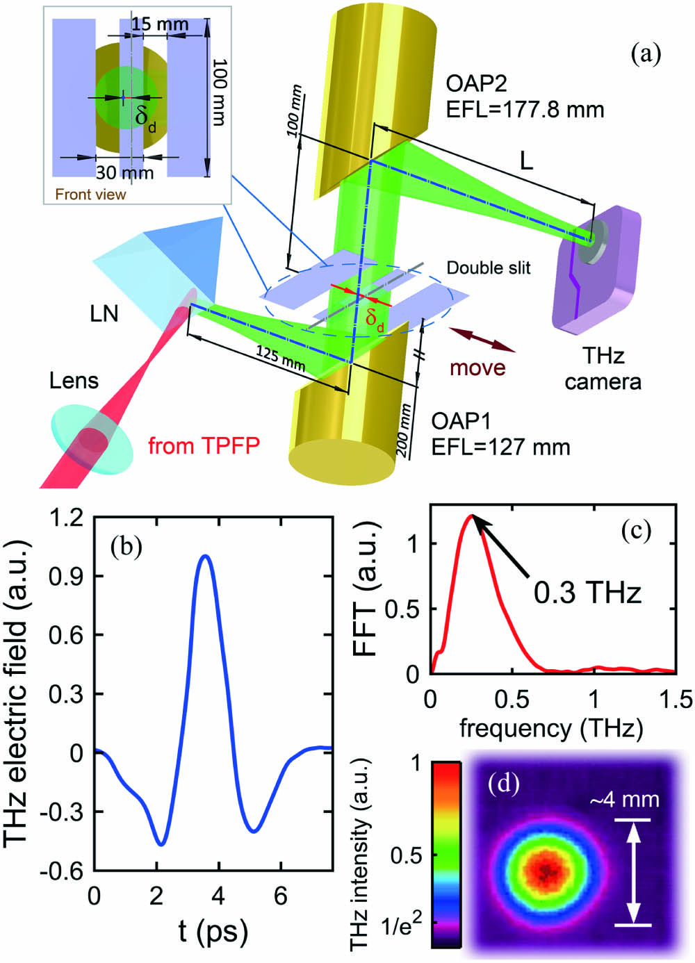
To realize the aforementioned diagnostic function, we implement the following experiments. The experimental setup is illustrated in Fig. 1(a). An intense terahertz beam source radiated from LN crystal driven by a commercial Ti:sapphire laser amplifier (Amplitude System, Pulsar 20, central wavelength 800 nm, pulse duration 30 fs, repetition rate 10 Hz) via the tilted-pulse-front technique is generated. Figures 1(b) and 1(c) plot the terahertz temporal waveform and its corresponding Fourier transform spectrum extracted from electro-optic single-shot measurement. The single-cycle terahertz pulse is , and its central frequency is with 0–1 THz frequency range. As is shown in Fig. 1(a), the emitted terahertz waves are collimated and focused into a terahertz camera (Spiricon, Pyrocam IV) by two off axis parabolic mirrors (OAPs), whose effective focal lengths (EFLs) are 5 in. and 7 in. (1 in. = 2.54 cm), respectively. Under 50 mJ single-pulse energy pumping, the generated terahertz energy is µ. A focused terahertz spot profile is shown in Fig. 1(d). The diameter of this spot is (), and the full width at half maximum (FWHM) is , which is very close to the calculated FWHM of the Airy spot of OAP2: , where is the EFL of OAP2, is the central wavelength of terahertz corresponding to 0.3 THz, and is the aperture of OAP2 and OAP1. The approach of diffraction limitation implies the optimized attitudes of OAPs. On this foundation, a copper double-slit apparatus with two gaps of 15 mm width, 30 mm period, and 0.2 mm thickness is inserted into the collimated terahertz beam to simulate the diffraction effect, as shown in the inset of Fig. 1(a). The double slit works like a wavefront-splitting interferometer, but the diffraction ought to be considered due to the relatively large size of gaps compared with the terahertz wavelength. Therefore, the presence of a double slit would transform the image received by the terahertz camera from Airy spots to patterns that are superpositions of interference and diffraction, and the position of the terahertz camera needs to be optimized () to obtain tight images. The choice of gap width is suitable for obtaining obvious diffraction patterns. When gaps are narrowed, secondary maximum spots are hard to detect because they are not intense enough.
Sign up for Chinese Optics Letters TOC. Get the latest issue of Chinese Optics Letters delivered right to you!Sign up now
Figure 1.Terahertz diffraction diagnostic system and the matched intense terahertz source. (a) Schematic diagram of the experimental setup for the terahertz diffraction method. (b) Typical terahertz temporal waveform and (c) its corresponding spectrum. (d) Focused terahertz beam profile recorded by a terahertz camera without the double slit when L.
With the aforementioned experimentally obtained diffraction diagnostics system and the intense terahertz source, we ought to analyze the modulation to diffraction patterns while inserting the double slit for the first step. A two-dimensional (2D) finite-difference time-domain (FDTD) simulation using the commercial software package (Lumerical FDTD, Lumerical Solutions Inc.) is carried out. In order to reduce computational load, we shrink the length of the collimated terahertz beam before the double slit (from 20 cm to 5 cm) in our simulation, and the change would not impact the authenticity of the simulation results. The computational domain is a rectangle and is discretized on zones (µ cell size). The evolution of the simulation is followed for 1.6 ns with perfectly matched layer (PML) boundary conditions. A Gaussian terahertz beam with a waist radius of 2.5 mm is normally incident into the domain and refocused by a pair of OAPs. The terahertz frequency distribution shows a Gaussian profile in Fig. 1(c), and the polarization direction is perpendicular to the page. The insets of Figs. 2(a)–2(c) show the deposited terahertz energy intensity distribution on the plane of the terahertz camera. When a movable double slit is inserted between OAPs, a series of diffraction patterns with regular variations are observed, as shown in Figs. 2(a)–2(c). When the centers for both the double slit and terahertz beam are perfectly overlapped, a bright beam spot accompanied by two weak diffraction patterns is symmetrically distributed on the left and right sides of the bright spot [see the inset of Fig. 2(b)]. When the double slit is deviated from the beam center, symmetry breakings happen, and asymmetrical diffraction patterns are formed [see Figs. 2(a) and 2(c)]. The variations of diffraction patterns are not difficult to understand, since the intensity of terahertz at the slits is modulated with the shifting double slit. Note that the wavefronts of the collimated terahertz beam are parallel to the double slit, and the phase difference between slits is zero. The experimental results [see the red line in the insets of Figs. 2(a)–2(c)] well reproduce the theoretical prediction. Thus, the asymmetry of the diffraction pattern could reveal the deviation of the terahertz beam and double slit qualitatively. Technically and quantitatively, we need to develop the inversion method like the Yang–Gu algorithm to deduce the terahertz beam profile on a double slit from the diffraction patterns gained by the terahertz camera. However, such a method is difficult to achieve, and we propose an alternative and uncomplicated way to portray the aforementioned modulation. In our simulation and experiments, we find that there is an apparent linear relationship between the double-slit position and the peak intensity position in diffraction patterns indicated by a dashed straight line in Fig. 2(d). This find is not incredible because it implies perturbative diffraction modulation when terahertz intensity is not symmetrical in gaps of the double slit. Experimental data points () are regression-fitted using the least square method, and slope parameter is introduced as describes perturbation of the central principal maximum in diffraction patterns caused by the relative movement between the collimated terahertz beam and double slit. Meanwhile, Eq. (1) is an empirical correlation, and we could apply the formula to derive the geometric relationship between the collimated terahertz beam and double slit facing a diffraction pattern gained by the terahertz camera. The linear relationship described in Eq. (1) must satisfy paraxial approximation, thus , where is the EFL of OAP2, and is the scope of the paraxial approximation. Moreover, since the transition motion for the double slit and the generated terahertz beam are relative, the diffraction method can be applied to diagnose the minute movement of the terahertz beam when the double-slit position is fixed. We can examine the idea for the next step.
Figure 2.Experimental and simulation results illustrating the relevance between terahertz diffraction patterns received by the terahertz camera and double-slit position. (a)–(c) Meridional diffraction fields and the corresponding diffraction patterns for different double-slit positions δd, 0, and 8 mm, respectively. (d) Peak intensity position δp in terahertz diffraction patterns as a function of double-slit position δd.
To verify the feasibility and spatial resolution sensitivity of the proposed diffraction method, we intentionally design a minute movement of the terahertz beam by inserting an iris with a variable diameter into the pumping beam before the tilted-pulse-front setup, as shown in Fig. 3(a). The IR pumping beam diameter is (). The maximum iris diameter is 50 mm. After modulation by the inserted iris, it illuminates onto a grating with a line density of 1500 lines/mm. The diffracted beam propagates through a lens () and illuminates the LN crystal. Owing to optical rectification (OR), the intense terahertz is excited by the tilted-front pump and emits from the rear surface (labeled as ). The terahertz wave is received by the diffraction diagnostics system in Fig. 1(a). In order to characterize the association between diffraction patterns and the movement of the terahertz beam more clearly and intuitively, we shift the double-slit position (), as is shown in Fig. 3(a), and the position of the double slit is locked hereafter. Figure 3(d) shows the experimental results of the double-slit diffraction diagnostics when varying the iris diameter Ø. When the iris diameter is fully open with a 50 mm diameter, the diffraction pattern is asymmetric with a brighter beam spot on the left side (A) of the principal beam spot (B). When the iris diameter decreases to 20 mm, the diffraction pattern tends to be symmetric with two uniform and bright spots around the main maximum. Further reducing the iris diameter to 15 mm, the spot A disappears, while the spot C is still obvious. Both spots A and C disappear and could not be detected when the iris diameter was smaller than 12 mm because the total energy of diffraction patterns received decreased sharply. Comparing with diffraction patterns in Figs. 2 and 3(d), we believe that the terahertz beam spot changes its location on the double slit when the iris is varied. The concrete direction of the terahertz beam is indicated in Fig. 3(a) by magenta lines when Ø, and the magenta arrows imply the movement of the terahertz beam direction when Ø is decreasing.
Figure 3.Diffraction diagnostics for monitoring the moving of the terahertz beam. (a) Experimental setup to diagnose tiny variations of the terahertz beam direction and position. (b) The pump shrinks and tilted terahertz wave is emitted when closing the iris. The green circle indicates the outline of the terahertz beam waist on the terahertz emitting surface of the LN crystal. The green Gaussian curve marked by the dashed-line arrow implies the intensity distribution of the terahertz beam when the iris is fully open. (c) Superior limit of the calculated terahertz beam profile on its emitting surface for different iris sizes. Dark purple line corresponds to Ø, blue 20 mm, and yellow 15 mm, respectively. (d) Experimental diffraction patterns received by the terahertz camera. (e) Extracted experimental movement of the terahertz beam compared with the theoretical calculations.
To explain these phenomena, we develop the unilaterally blocked Gaussian beam model illustrated in Figs. 3(b)–3(c). According to the previous experiments in our team[15,16], the pump beam center and the terahertz beam center are not coincident, and the distance between them is . Meanwhile, the distance between the pump spot centrum on and its nearest edge of the LN prism is 12.0 mm. To clarify these geometric relationships, we set up coordinate axis considering the pump spot center as the original point. Thus, the coordinate of the terahertz beam center . When closing the iris, the asymmetry geometry leads to the unilaterally blocked effect, which means the terahertz intensity would be weakened due to the absence of OR on the region where the pump is blocked. The blocked region expands toward the direction of increasing and finally covers the whole terahertz spot. This effect will reshape the terahertz spot profile on surface , as shown in Fig. 3(c). (i) When [ is the deviation between the coordinate of vertex D labeled in Fig. 3(b) and ; closing the iris drives vertex D to move toward the direction of increasing , and correspondingly changes from negative to positive], the region of pump is not blocked, and the terahertz intensity is subject to Gaussian distribution as (ii) When , the region of the pump is blocked, and the terahertz intensity satisfies the following inequality: where and are the intensity absorption coefficient and phase matching angle of the LN crystal, respectively. is the horizontal radius () of the terahertz spot [15]. The reshaped terahertz Gaussian beam with deficiency would no longer propagate along the direction perpendicular to the surface , and it would emit a tilted beam indicated by inclination in Fig. 3(b). To be more precise, we conduct series 2D FDTD simulations to model the propagation of the reshaped terahertz beam and exploit it to resolve the unequal relation [indicated by the blue curve in Fig. 3(e) on condition of ]. Thus, the experimental curve should lie within the region marked by the nattier blue. Meanwhile, we can extract the relation from the experimental diffraction patterns [indicated by the red curve in Fig. 3(e)]. The two curves can be depicted in one graph because their coordinates are correlated. When satisfies the small-angle approximation, the approximate expressions are listed as where is the EFL of OAP1, is the movement of peak intensity of the terahertz beam on the plane of the double slit, and is the linearity coefficient between Ø and . As is shown in Fig. 3(e), the experimental data are within theoretical predictions. When Ø, the symmetry of the terahertz beam profile on is partially restored, as indicated by the yellow line in Fig. 3(c). Thus, reaches saturation in the experiment, while the simulated curve increases exponentially due to assuming . The detected maximum varieties of feature parameters () and () are close to the limit resolutions listed in Table 1. This paragraph exhibits an application of the proposed diffraction diagnostic method to explore the physics of the intense terahertz sources generated by TPFP and inspect the spatial resolutions.
Parameters
Resolution
Descriptions
δp
80 µm
Resolution of THz camera
δc
1.1 mm
Δδc = Δδcd =Δδp/β
α
0.50°
Calculated by Eq. (4)
Table 1. Resolutions of Feature Parameters of the Proposed Terahertz Diffraction Diagnostic Method
Furthermore, with this method, we can also estimate the terahertz central frequency. According to the Young’s double-slit inter-reference experiments, the first-order diffraction angle , where is the first-order diffraction pattern position. The estimated central wavelength , the corresponding estimated frequency is , and is the distance between gaps. Compared with the calculated central wavelength (1.0 mm) obtained in the electro-optic single-shot measurement [see Fig. 1(c)], the estimated value is a little smaller. This error is acceptable because diffraction must be considered due to the relatively large size of gaps compared with the terahertz wavelength. Therefore, Young’s stripe equation must be ameliorated in our experiments.
3. Conclusion
In summary, we introduce an effective terahertz diffraction method to diagnose the movement of the terahertz beam position and direction generated from the LN crystal via the tilted-pulse-front technique. The proposed method in theory could detect the minute revolvement of the emitted angle () and displacement () of the divergent and collimated terahertz beams, respectively. To corroborate these spatial resolutions, we fabricate a revolvement of the emitted angle of the terahertz beam via inserting an iris into the IR pumping beam before it enters into the tilted-pulse-front setup. The movement of the terahertz beam is detected by the diffraction diagnostic system and well explained by the unilaterally blocked Gaussian beam model. The applicable range of the terahertz diffraction diagnostic method provided in this paper is not confined to terahertz generated by TPFP. For some specific terahertz sources or terahertz application occasions with spatial fluctuations, such as terahertz emitted from water lines[17] or terahertz transmitted in water vapor[18], this method is suitable to monitor variations of terahertz beam position and direction.