
Guanli Wang, Tigang Ning, Jingjing Zheng, Jing Li, Jian Xu, Huai Wei, Li Pei, Shaoshuo Ma. Novel Bend-Resistant Large-Mode-Area Fan-Segmented Cladding Fiber with Double Trenches[J]. Acta Optica Sinica, 2019, 39(10): 1006008
- Acta Optica Sinica
- Vol. 39, Issue 10, 1006008 (2019)
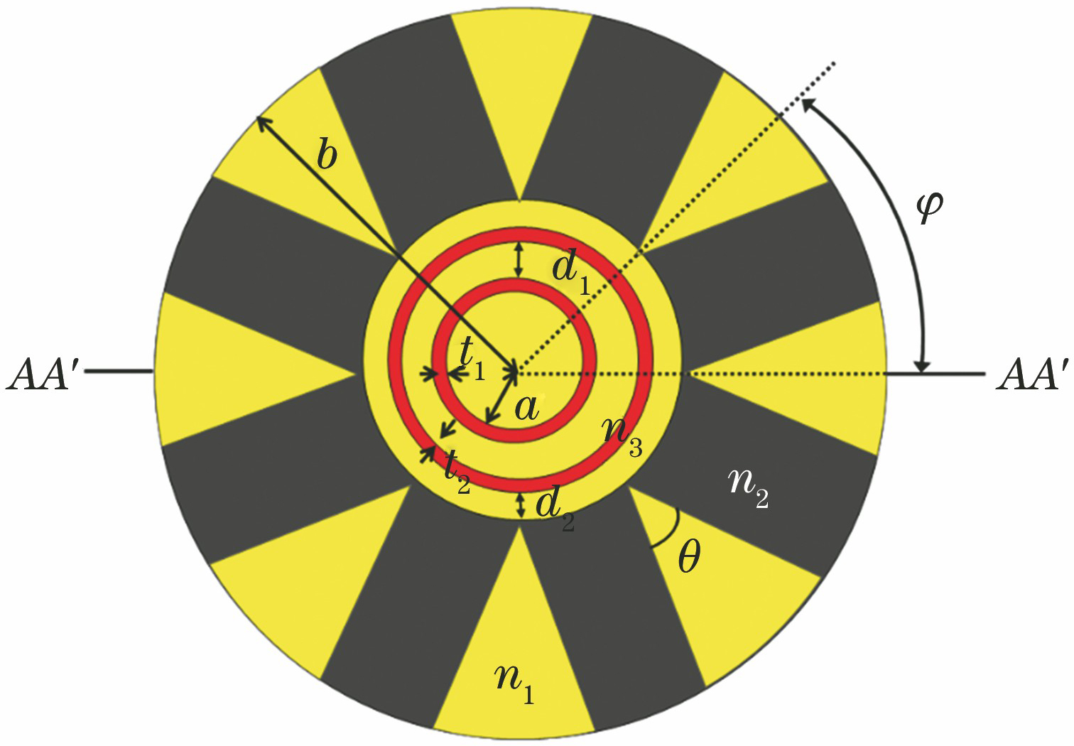
Fig. 1. Structure of double-trench-assisted fan-segmented cladding fiber
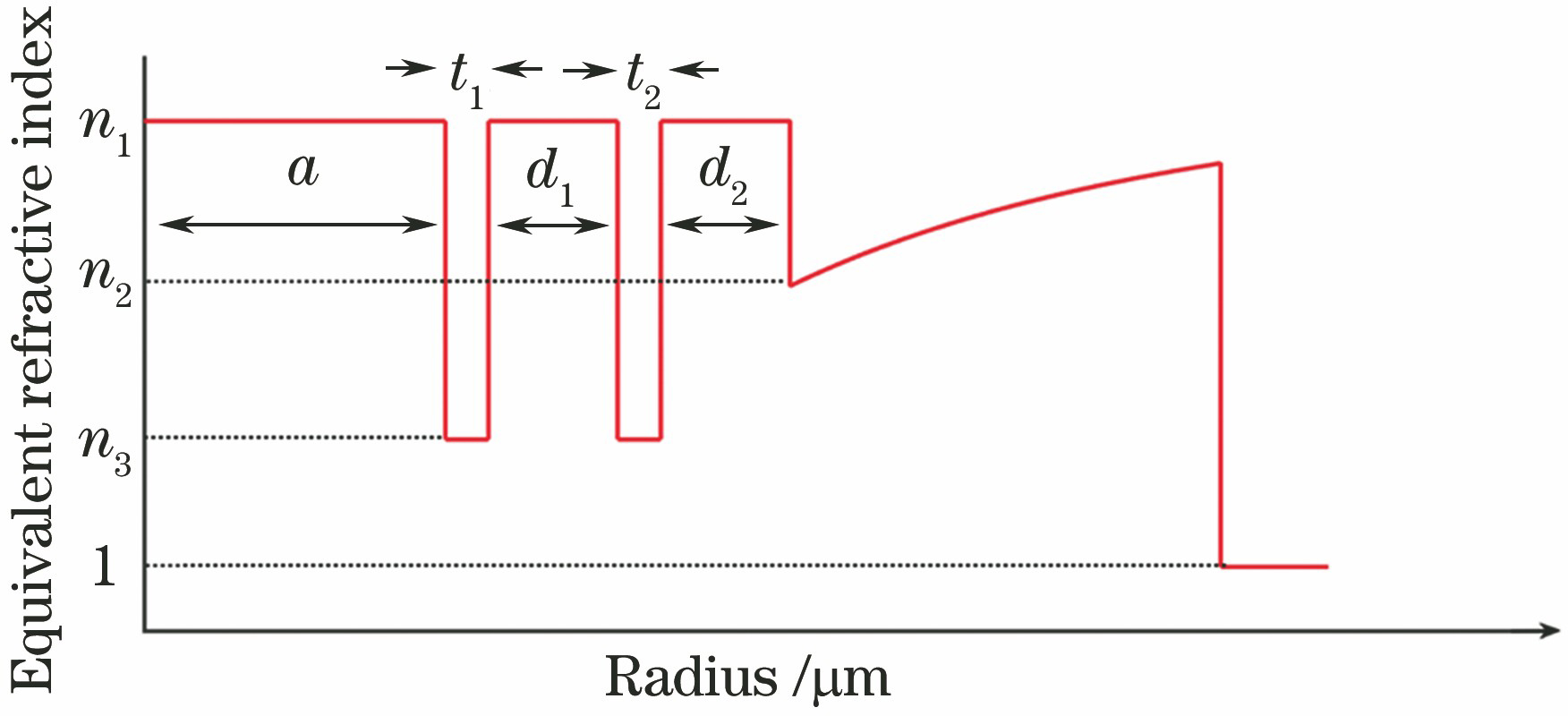
Fig. 2. Equivalent refractive index profile of double-trench-assisted fan-segmented cladding fiber
Fig. 3. Structures of fan-segmented cladding fibers. (a) ST-FSCF; (b) FSCF
Fig. 4. Effect of core radius on fiber properties. (a) Leakage loss as a function of core radius; (b) mode area and loss ratio as functions of core radius
Fig. 5. Effect of bending orientation on fiber properties. (a) Leakage loss as a function of bending orientation; (b) mode area and loss ratio as functions of bending orientation
Fig. 6. Mode field distributions of LP01, LP11v, LP11h, and LP21 modes at different bending orientations. (a) φ =0°; (b) φ =22.5°
Fig. 7. Effect of bending radius on fiber properties. (a) Leakage loss as a function of bending radius; (b) mode area and loss ratio as functions of bending radius
Fig. 8. Bending loss and mode area as functions of trench width. (a) t 1; (b) t 2
Fig. 9. Bending loss and mode area as functions of resonant ring thickness. (a) d 1; (b) d 2
Fig. 10. Effect of wavelength on fiber properties. (a) Leakage loss as a function of wavelength; (b) mode area and loss ratio as functions of wavelength
Fig. 11. Bending loss and mode area as functions of index difference. (a) Δn 1; (b) Δn 2
Fig. 12. Combined effect of resonant ring thicknesses d 1 and d 2 on fiber properties. (a) Loss of FM; (b) minimal loss of HOM; (c) loss ratio
|
Table 1. Comparison of properties of current work (DT-FSCF) and previous works (FSCF,ST-FSCF)

Set citation alerts for the article
Please enter your email address
© Copyright 2018-2021 | Chinese Laser Press. All Rights Reserved 沪ICP备15018463号-20