
Qi Liu, Seeram Ramakrishna, Yun-Ze Long. Electrospun flexible sensor[J]. Journal of Semiconductors, 2019, 40(11): 111603
- Journal of Semiconductors
- Vol. 40, Issue 11, 111603 (2019)
Abstract
1. Introduction
Flexible sensors have been widely used in various types of electronic devices. Their advantage lies in their high flexibility, ability to adapt to various complex environments, and broad development prospects. Flexible sensors with nanomaterials have a larger specific surface area to further enhance sensor performance. There are several ways to make nanomaterials. Among them, electrospinning provides a low-cost, large-scale method for preparing flexible nanofibers. The morphology of the fibers can be adjusted during the electrospinning process to obtain different structures[
In this review, we summarize the progress in the preparation of flexible sensors by electrospinning. Photodetectors, stress sensors, gas sensors and nanogenerators were introduced. The prospect of flexible sensors and electrospinning were discussed towards the end.
2. Electrospinning
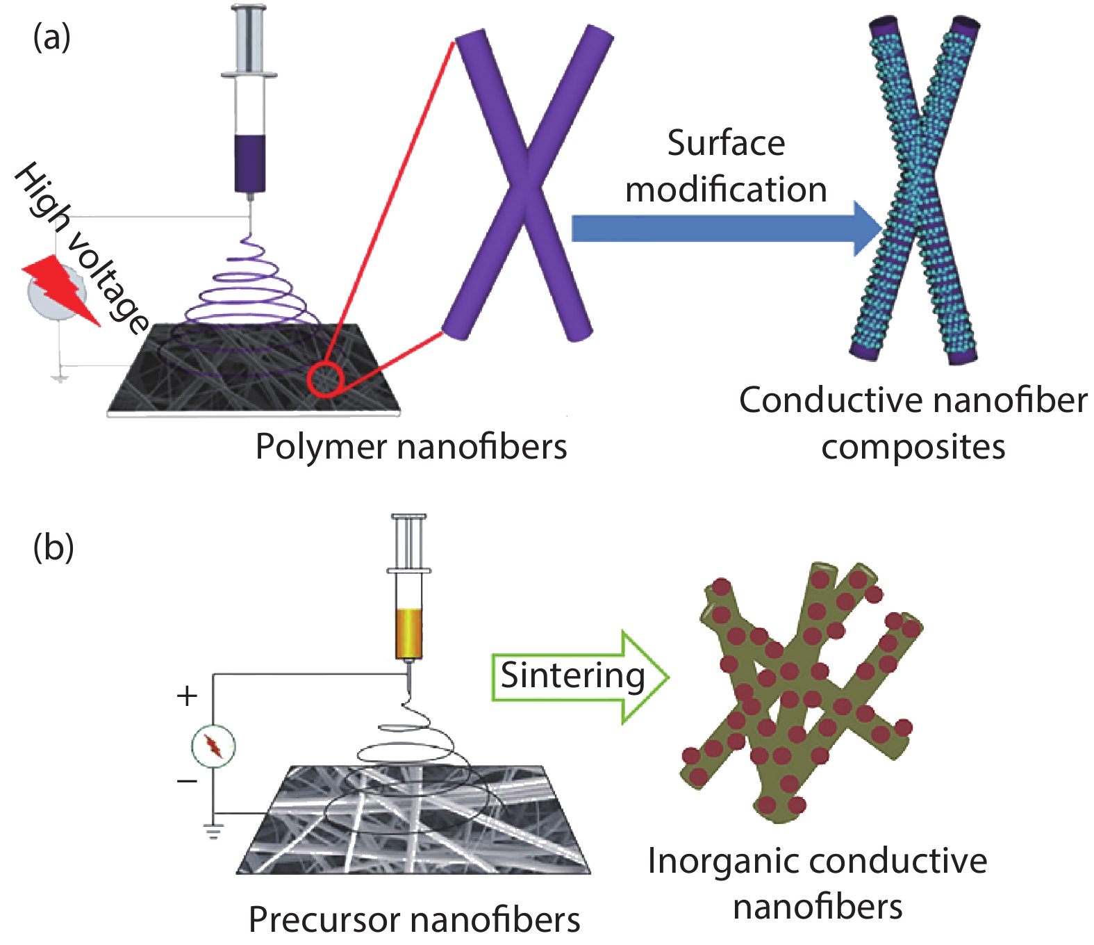
Electrospinning devices typically consist of a propulsion pump, a high voltage power supply, and a collection plate. When the voltage applied at the end of the needle exceeds a certain critical value, the charge repulsion on the surface of the solution exceeds its surface tension, and the jet formed at the end of the needle is deposited on the collecting plate under the action of an electric field to form a fiber membrane. The parameters used in the electrospinning process will affect the morphology of the fiber to some extent. An increase in the spinning voltage, a decrease in the advancement speed, and an increase in the distance between the electrodes and the collection plate can reduce the diameter of the resulting nanofiber. There are usually two methods for preparing conductive nanofibers by electrospinning, as shown in Fig. 1[
![]()
Figure 1.(Color online) (a) Flowchart for preparing conductive nanofibers by surface modification[
3. Strategies for preparing conductive nanofibers
3.1. Surface treatment
An electrospun fiber is used as a template, and a metal material such as gold or copper is deposited thereon to obtain a conductive fiber. The electrospinning film can also be removed by sintering, dissolution, or the like in a subsequent step. Similarly, conductive fibers can also be obtained by chemically depositing or coating a polymer conductive material, carbon nanotubes or the like onto the surface of the fiber membrane. This method of treating only the surface of the fiber causes the conductive material to form a cylindrical structure, increase the specific surface area, and have a certain conductivity. This also increases their sensitivity as a gas sensor.
3.2. Precursor heat treatment
Conductive fibers can also be obtained by heat treating a precursor of a certain material. For example, the carbon fiber is obtained by electrospinning a polyacrylonitrile (PAN) solution of N,N-dimethylformamide (DMF) and heat treatment. Mixing a precursor thereof with a polymer solution and electrospinning, then sintering in an air atmosphere to remove components such as a polymer can obtain an inorganic oxide fiber. This method can completely remove the polymer component and obtain a continuous conductive fiber.
4. Application
4.1. Photodetector
Due to its photoelectric effect, semiconductors can be exposed to light and cause a change in conductivity. The light intensity can be characterized by changes in material current. Zhang et al.[
![]()
Figure 2.(Color online) (a) Schematic diagram of field effect test device for zinc oxide fiber. (b) Field effect characteristics of Ce-doped ZnO[
![]()
Figure 3.(Color online) (a) Schematic of the printing unit. (b) Time-domain optical response of the ZnO fiber array. (c)
4.2. Stress sensor
The conductive fiber membrane prepared by electrospinning is easily changed under pressure for the variation of shape, and the electrical resistance of the fiber membrane is also changed. Therefore, the change in the current of the conductive fiber membrane can characterize the change in the corresponding stress[
![]()
Figure 4.(Color online) (a)
A silver-loaded alginate stress sensor was prepared by Hu et al.[
![]()
Figure 5.(Color online) (a) Electrical performance of the sensor at different pressures. (b) Current change of the sensor at different pressures. (c) Response of the sensor to human respiration. (d) Response of the sensor to “Nano” and “Perfect”. (e) Electrode array diagram. (f) Pressure distribution[
4.3. Gas sensor
Due to its structural advantages, the large specific surface area and high porosity allow rapid gas detection, and the nano-conductive fiber membranes are well suited for use as gas sensors. Zinc oxide has a special shape and is widely used in various types of sensors. Zhang et al.[
![]()
Figure 6.(Color online) (a) PEDOT:PSS/PVP composite nanofibers response to CO. (b) PEDOT:PSS/PVP composite nanofibers response to different concentrations of CO[
The diameter of nanofibers affects their sensing properties. Zhang et al.[
![]()
Figure 7.(Color online) (a) SEM image of ultrafine fiber. (b) Particle size distribution of ultrafine fiber. (c, d) Ammonia response curve of traditional electrospun fiber. (e, f) Ammonia response curve of microfiber[
Zhang et al.[
![]()
Figure 8.(Color online) (a) Photo of the mask combined with the sensor. (b) Response in normal and running state. (c) Response in joy state. (d) Response in sad state. (e) Response in sleep state. (f) Response in normal breathing (NB) and hard to breathe (HB) conditions[
4.4. Nanogenerator
Nano-generators can convert small-scale environmental energy into electrical energy, and self-powered systems based on nano-generators will be a good choice for reducing the size of electronic devices. On the other hand, the strength of the output signal of the nanogenerator is related to pressure and temperature, and can be used as a self-powered sensor. Due to its portability and self-powered features, there are many applications in the field of wearable devices. You et al.[
![]()
Figure 9.(Color online) (a) Piezoelectric properties of PVDF under pressure. (b) Piezoelectric properties of PVDF during bending. (c) Pyroelectric characteristics of PVDF. (d) Mixed output of piezoelectric signals and pyroelectric signals of PVDF[
![]()
Figure 10.(Color online) (a) Electronic skin map and wiring diagram. (b) Piezoelectric properties of electronic skin under pressure. (c) Piezoelectric properties of electronic skin during bending. (d) Pyroelectric characteristics of electronic skin[
![]()
Figure 11.(Color online) (a) Pressure profile. (b) Temperature profile. (c) Output of electronic skin after short-circuit of adjacent components. (d) Output signal of direct short-circuit of resistor unit. (e) Output of resistor unit in short-circuit condition of adjacent components[
Guo et al.[
![]()
Figure 12.(Color online) (a) Bluetooth device schematic. (b) Software interface diagram. (c) Wireless signal when squatting. (d) Wireless signal while walking. (e) Wireless signal during running. (f) Effect of BaTiO3 content on piezoelectricity. (g) 3% BaTiO3 The piezoelectricity of the PVDF fiber membrane at different frequency impacts[
![]()
Figure 13.(Color online) (a) Triboelectric nanogenerator structure diagram. (b) Open circuit voltage output. (c) Breathing output signal. (d) Finger click output signal[
5. Summary
Flexible sensors composed of conductive nanofibers exhibit outstanding performance. The large-scale and low-cost development of high-performance conductive nanomaterials will greatly promote the development of flexible sensors. Of course, electrospinning technology is an alternative solution. Electrospinning technology can control the fiber diameter and even produce fibers with a diameter of less than 1 nm[
Acknowledgements
This work was supported by the National Natural Science Foundation of China (Nos. 51673103 and 51973100).
References
[1] J Zheng, Y Z Long, B Sun et al. Polymer nanofibers prepared by low-voltage near-field electrospinning. Chin Phys B, 21, 048102(2012).
[2] J Zheng, B Sun, Y Z Long et al. Fabrication of nanofibers by low-voltage near-field electrospinning. Adv Mater Res, 486, 60(2012).
[3] X X He, J Zheng, G F Yu et al. Near-field electrospinning: progress and applications. J Phys Chem C, 121, 8663(2017).
[4] W Y Si, H D Zhang, Y J Liu et al. Fabrication and pressure sensing analysis of ZnO/PVDF composite microfiber arrays by low-voltage near-field electrospinning. Chem J Chin Univ-Chin, 38, 997(2017).
[5] M H You, X X Wang, X Yan et al. A self-powered flexible hybrid piezoelectric-pyroelectric nanogenerator based on non-woven nanofiber membranes. J Mater Chem A, 6, 3500(2018).
[6] J X Sui, X X Wang, C Song et al. Preparation and low-temperature electrical and magnetic properties of La0.33Pr0.34Ca0.33MnO3 nanofibers via electrospinning. J Magnet Magnet Mater, 467, 74(2018).
[7] H Shen, L Li, D Xu. Preparation of one-dimensional SnO2–In2O3 nano-heterostructures and their gas-sensing property. RSC Adv, 7, 33098(2017).
[8] S Chen, Y Z Long, H D Zhang et al. Fabrication of ultrathin In2O3 hollow fibers for UV light sensing. Phys Scrip, 89, 115808(2014).
[9] S Chen, M Yu, W P Han et al. Electrospun anatase TiO2 nanorods for flexible optoelectronic devices. Rsc Adv, 4, 46152(2014).
[10] M H You, X Yan, J Zhang et al. Colorimetric humidity sensors based on electrospun polyamide/CoCl2 nanofibrous membranes. Nanoscale Res Lett, 12, 360(2017).
[11] J Y Pyo, W J Cho. In-plane-gate a-IGZO thin-film transistor for high-sensitivity pH sensor applications. Sens Actuators B, 276, 101(2018).
[12] S Li, J Zhang, D D Ju et al. Flexible inorganic composite nanofibers with carboxyl modification for controllable drug delivery and enhanced optical monitoring functionality. Chem Eng J, 350, 645(2018).
[13] J Zhang, S Li, D D Ju et al. Flexible inorganic core-shell nanofibers endowed with tunable multicolor upconversion fluorescence for simultaneous monitoring dual drug delivery. Chem Eng J, 349, 554(2018).
[14] S Chen, G S Liu, H W He et al. Physical structure induced hydrophobicity analyzed from electrospinning and coating polyvinyl butyral films. Adv Conden Matter Phys, 2019, 6179456(2019).
[15] G S Liu, X Yan, F F Yan et al. In situ electrospinning iodine-based fibrous meshes for antibacterial wound dressing. Nanoscale Res Lett, 13, 309(2018).
[16] X Yan, u M Yu, a S Ramakrishna et al. Advances in portable electrospinning devices for in situ delivery of personalized wound care. Nanoscale(2019).
[17] H Liu, Z G Zhang, X X Wang et al. Highly flexible Fe2O3/TiO2 composite nanofibers for photocatalysis and utraviolet detection. J Phys Chem Solids, 121, 236(2018).
[18] J Zhang, X X Wang, B B Zhang et al. In situ assembly of well-dispersed Ag nanoparticles throughout electrospun alginate nanofibers for monitoring human breath-smart fabrics. Acs Appl Mater Interfaces, 10, 19863(2018).
[19] H D Zhang, M Yu, J C Zhang et al. Fabrication and photoelectric properties of La-doped p-type ZnO nanofibers and crossed p–n homojunctions by electrospinning. Nanoscale, 7, 10513(2015).
[20] S Liu, S L L Liu, Y Z Long et al. Fabrication of p-type ZnO nanofibers by electrospinning for field-effect and rectifying devices. Appl Phys Lett, 104, 042105(2014).
[21] Y J Liu, H D Zhang, J Zhang et al. Effects of Ce doping and humidity on UV sensing properties of electrospun ZnO nanofibers. J Appl Phys, 122, 105102(2017).
[22] X Liu, L L Gu, Q P Zhang et al. All-printable band-edge modulated ZnO nanowire photodetectors with ultra-high detectivity. Nat Commun, 5, 4007(2014).
[23] H D Zhang, Y J Liu, J Zhang et al. Electrospun ZnO/SiO2 hybrid nanofibers for flexible pressure sensor. J Phys D, 51, 085102(2018).
[24] L Tong, X X Wang, X X He et al. Electrically conductive TPU nanofibrous composite with high stretchability for flexible strain sensor. Nanoscale Res Lett, 13, 86(2018).
[25] G F Yu, X Yan, M Yu et al. Patterned, highly stretchable and conductive nanofibrous PANI/PVDF strain sensors based on electrospinning and in situ polymerization. Nanoscale, 8, 2944(2016).
[26] W P Hu, B Zhang, J Zhang et al. Ag/alginate nanofiber membrane for flexible electronic skin. Nanotechnology, 28, 445502(2017).
[27] H D Zhang, Y Z Long, Z J Li et al. Fabrication of comb-like ZnO nanostructures for room-temperature CO gas sensing application. Vacuum, 101, 113(2014).
[28] H D Zhang, X Yan, Z H Zhang et al. Electrospun PEDOT:PSS/PVP nanofibers for CO gas sensing with quartz crystal microbalance technique. Int J Polym Sci, 2016, 3021353(2016).
[29] H D Zhang, C C Tang, Y Z Long et al. High-sensitivity gas sensors based on arranged polyaniline/PMMA composite fibers. Sens Actuators A, 219, 123(2014).
[30] C H Sheng, H D Zhang, S S Chen et al. Fabrication, structural and humidity sensing properties of BaTiO3 nanofibers via electrospinning. Int J Modern Phys B, 29, 1550066(2015).
[31] Q Q Zhang, X X Wang, J J Fu et al. Electrospinning of ultrafine conducting polymer composite nanofibers with diameter less than 70 nm as high sensitive gas sensor. Materials, 11, 1744(2018).
[32] X X Wang, W Z Song, M H You et al. Bionic single-electrode electronic skin unit based on piezoelectric nanogenerator. Acs Nano, 12, 8588(2018).
[33] W Z Guo, C X Tan, K M Shi et al. Wireless piezoelectric devices based on electrospun PVDF/BaTiO3 NW nanocomposite fibers for human motion monitoring. Nanoscale, 10, 17751(2018).
[34] H J Qiu, W Z Song, X X Wang et al. A calibration-free self-powered sensor for vital sign monitoring and finger tap communication based on wearable triboelectric nanogenerator. Nano Energy, 58, 536(2019).
[35] C Huang, S Chen, C Lai et al. Electrospun polymer nanofibres with small diameters. Nanotechnology, 17, 1558(2006).
[36] R Yang, J He, L Xu et al. Bubble-electrospinning for fabricating nanofibers. Polymer, 50, 5846(2009).
[37] S Jian, J Zhu, S Jiang et al. Nanofibers with diameter below one nanometer from electrospinning. RSC Adv, 8, 4794(2018).

Set citation alerts for the article
Please enter your email address
© Copyright 2018-2021 | Chinese Laser Press. All Rights Reserved 沪ICP备15018463号-20