• Chinese Optics Letters
  • Vol. 17, Issue 12, 121101 (2019)
Yongfeng Zhang1、2、3 and Hao Xian1、2、*
Author Affiliations
  • 1Key Laboratory on Adaptive Optics, Chinese Academy of Sciences, Chengdu 610209, China
  • 2Institute of Optics and Electronics, Chinese Academy of Sciences, Chengdu 610209, China
  • 3University of Chinese Academy of Sciences, Beijing 100049, China
  • show less
    DOI: 10.3788/COL201917.121101 Cite this Article Set citation alerts
    Yongfeng Zhang, Hao Xian. Piston sensing via a dispersed fringe sensor with a merit-function-based active scanning algorithm at low light levels[J]. Chinese Optics Letters, 2019, 17(12): 121101 Copy Citation Text show less

    Abstract

    Dispersed fringe sensors are a promising approach for sensing the large-scale physical step between adjacent segments with acceptable accuracy. However, the nature of dispersion in a dispersed fringe sensor leads to the ideal dispersed fringe pattern becoming vulnerable to noise, particularly at low light levels. A reliable merit-function-based algorithm with an active actuation is introduced here. The feasibility of our algorithm is numerically demonstrated, and Monte Carlo experiments for different signal-to-noise ratios are conducted to assess its robustness. The results show that the method is valid even when the signal-to-noise ratio is as low as 1.

    It has been a trend that a segmented mirror is employed to construct extremely large telescopes. Up to this date, several large segmented telescopes have been completed, such as the Keck I/II[1], Giant Magellan Telescope (GMT)[2], South African Large Telescope (SALT)[3], Hobby-Eberly Telescope (HET)[4], and Large Sky Area Multi-Object Fiber Spectroscopic Telescope (LAMOST)[5]; and several programs are being planned, such as the Thirty Meter Telescope (TMT)[6], European Extremely Large Telescope (E-ELT)[7], and Advanced Technology Large-Aperture Space Telescope (ATLAST)[8]. For the purpose of making a segmented mirror act as an equivalent monolithic mirror, the rigid misalignment errors in the segmented mirror must be corrected within the tolerance limit, especially the piston error; if not, the image quality will not be better than that of a single segment[9].

    Over the past decades, many effective methods have been proposed and demonstrated in indoor and on-sky experiments. The broadband/narrow-band algorithm[10,11], APE experiment[12], dispersed fringe sensing (DFS) method[13,14], and the phase diversity (PD) or phase retrieval (PR) algorithm[15,16] all achieved great success in co-phasing the segments. However, in terms of capture range, the DFS method shows great superiority over other schemes, which makes it applicable for the commission of the James Webb Space Telescope (JWST)[17], a spaced-based, deployable telescope. The DFS shares the same geometry as that of broadband/narrow-band algorithms, other than the introduction of a dispersion element. The capture range could be flexibly adjusted by substituting a dispersion element with a different dispersion power. All of these advantages make DFS the promising approach for large-scale piston sensing.

    Due to the inherent feature of spatially dispersing the broadband light over a broad range, with limited photons passing through the sub-aperture, the photon events in each pixel would be less and less, which makes DFS extremely vulnerable to noise contamination. The information available would be lost in the noisy background, which is more serious for low light level cases. Traditional algorithms for extraction of piston error from a dispersed fringe pattern (DFP), such as the least-squared fitting (LSF) method[18], frequency peak location (FPL) method[19], and main peak position (MPP) method[20] would be invalid for a strongly noisy DFP. Despite the fact that the dispersed-fringe-accumulation-based left-subtract-right (DFA-LSR) method proposed by Li et al. is suited for noisy DFP[21], its capture range is limited to within a half of the minimum wavelength used. In this Letter, a merit-function-based active scanning algorithm is introduced to overcome the destructive influence of strong noise, and at the same time preserve the ability of large-scale sensing.

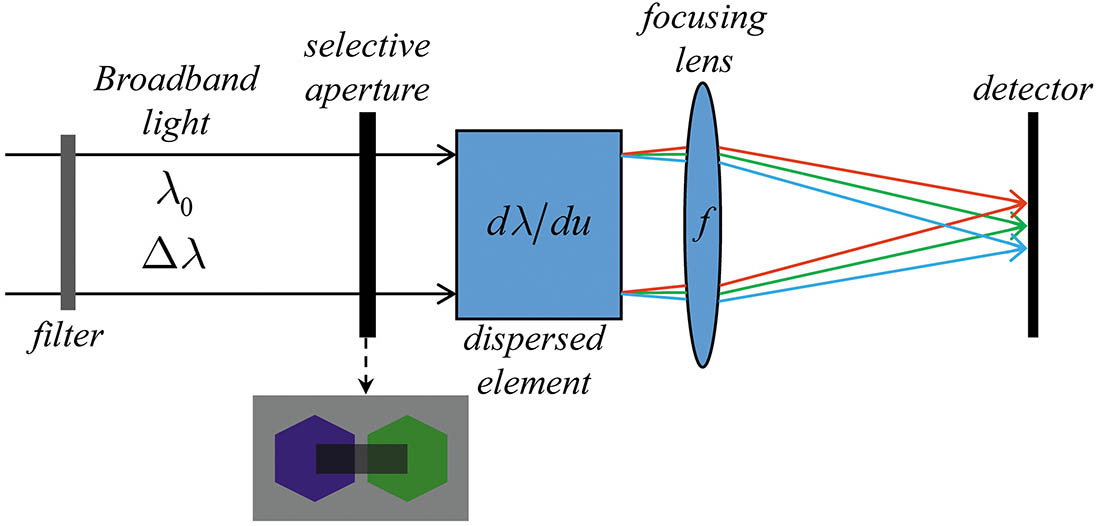
    A geometry of DFS is shown in Fig. 1. For simplicity, we use a selective aperture with a rectangular hole for sampling the intersegment part of the segmented mirror.

    Geometry of DFS.

    Figure 1.Geometry of DFS.

    When DFS is incident with the broadband light, with central wavelength λ0, bandwidth Δλ, and spectral weight S(λ), the intensity distribution in the image plane resulting from a dispersion element with dispersion coefficient C, which stands for the change of wavelength per spatial separation, is expressed as h(u)=λ0Δλ/2λ0+Δλ/2S(λ)hm[uu(λ),v;λ]dλ,where u=(u,v) is the position vector in the image plane and hm(u;λ) is the far-field intensity for monochromatic light without dispersion, and given by hm(u;λ)=[X(YG)λf]2sinc2(Xuλf)sinc2[(YG)v2λf]×cos2[2πλ(Y+G4vf+p)],where X, Y are the lengths of selective aperture along the dispersion and interference direction, respectively, G is the gap between the adjacent segments, f is the focal length, and p is the piston error. In addition, u(λ) in Eq. (1) is the dispersion displacement for wavelength λ, which could be determined by λ(u)=λ0+dλduu=λ0+Cu.A distinct feature of DFS is that the limited photons passing through the system are spread across the focal plane because of the dispersion effect. In each ideal DFP corresponding to a given piston, the peak value is extremely low. For the purpose of analysis, a quantity is defined as R=max[h(u,v)]u,vh(u,v).

    In order to obtain a further understanding of the unfavorable effect of dispersion, the quantity R for the case without dispersion, i.e., C=, is chosen as a comparison. The parameters used in analysis are listed in Table 1. What needs to be emphasized is that the parameters shown in Table 1 are throughout this Letter, and the results are shown in Fig. 2.

    X (mm)Y (mm)G (mm)f (mm)C(nm/mm)λ0 (nm)Δλ (nm)
    273100100/1.236750100

    Table 1. Parameters Used for Analysis of J as a Function of Piston Error

    Relation between R and the piston error for cases with and without dispersion.

    Figure 2.Relation between R and the piston error for cases with and without dispersion.

    Obviously, the quantity R is evidently larger when the piston error is nearly eliminated. The ratio for a case without dispersion is more than an order of magnitude larger than that for a case with dispersion. This fact that each pixel in DFP is with extremely low effective photon events makes DFS vulnerable to random noise is a direct motivation to develop a robust algorithm for sensing large-scale piston error from strongly noisy DFP with enough accuracy.

    Li et al. proposed the DFA-LSR algorithm to cope with the fine co-phasing problem in strong noise. However, it depends on the reliable left and right peak values after accumulation along the dispersion direction. When the absolute value of piston error is larger than one quarter of the minimum wavelength, the characteristic peaks would disappear, thus, this algorithm becomes invalid. In order to make up for this technical vacancy, a merit-function-based active scanning algorithm is introduced. It makes full use of the actuators attached to the back of the segment to actively actuate one of the segments in question. Figure 3 shows the flow chart of our algorithm. The process of our algorithm can be divided into two parts. The first step is to collect all of the DFPs corresponding to each actuated position within the stroke of actuators, and thus, a data cube of DFPs for different pistons could be readily obtained. In the second step, the merit function value is evaluated for each DFP. The actuation displacement corresponding to the maximum of the merit function values is equal to the negative of the actual piston error and could be directly applied to correct the piston misalignment.

    Flow chart of the algorithm introduced in this Letter.

    Figure 3.Flow chart of the algorithm introduced in this Letter.

    There are many merit function definitions available[22,23], and we employ the sum of the n-th power of the intensity as our merit function for its computational simplicity, i.e., Jn=u,vhn(u,v),where Jn is obtained by summation over the whole DFP. It has been proved that for the monochromatic case, Jn reaches its maximum only when the aberration function is reduced to no more than the image translation[22]. For the problem described here, the monochromatic Jn would be maximum when the piston error is completely eliminated. As for DFP, it is a desperately tough task to theoretically prove this similar conclusion. So, a numerical analysis is conducted to testify that, alternatively. The result of Jn as a function of piston error is shown in Fig. 4. Here, two spectral weight functions are used.

    Jn as a function of piston error, for (a) a uniform spectrum, (b) the random spectrum, (c) for the random spectrum shown in (b).

    Figure 4.Jn as a function of piston error, for (a) a uniform spectrum, (b) the random spectrum, (c) for the random spectrum shown in (b).

    It could be seen that the maximum is reached when the piston error is zero, not only for a uniform spectrum, but also for a random spectrum. It is indicated that the merit function defined as Eq. (5) could be used as the indicator whether or not the in-phase state is achieved. The larger the power exponent is, the smaller the minimum of relative merit function is. As a result, the dynamic range of the relative merit function is satisfactorily broadened by adopting the larger power exponent.

    As an example for describing the algorithm developed here, we assume here that the segments are actively actuated by three actuators in the piston, each of which is within a range of 100 μm, and a resolution of 0.5 nm, and the segment could deviate from the ideal position in the +/ direction with a maximum displacement of 50 μm. In addition, a piston error of 42 μm exists in the two-segment segmented mirror. The signal for this disturbed status is plotted in Fig. 5.

    Signal for a piston error of 42 μm. When the displacement of the actuator is −42 μm, the normalized merit function reaches its maximum.

    Figure 5.Signal for a piston error of 42 μm. When the displacement of the actuator is −42 μm, the normalized merit function reaches its maximum.

    The displacement corresponding to the maximum of the normalized merit function is eventually equal to the negative of the ideal piston error. The approach proposed in this Letter is simple to implement, and in general, the piston error could be effectively and accurately sensed provided that the value of error is within the range of the actuator; thus, it is free of the special requirements in the traditional methods, such as the optimal fringe extraction line[24], a clear main peak profile in the spatial domain[20,21] or the spatial frequency domain[19]. In the following, we will give an analysis of its robustness to noise. The signal-to-noise ratio (SNR) is defined as[25]SNR=Pσn,where P is the peak value of the DFP without noise and σn is the standard deviation value of the noise. Two realizations of noisy DFP for a piston error of 15 μm for different SNRs are shown in Fig. 6. It is obvious that the DFP would suffer from the destructive effect from noise, which is especially severe for strong noise commensurate with an ideal intensity of DFP.

    Two realizations of noisy DFP for different SNRs: (a) SNR is 1, (b) SNR is 5.

    Figure 6.Two realizations of noisy DFP for different SNRs: (a) SNR is 1, (b) SNR is 5.

    Essentially, the problem of how the noises with different levels affect the piston sensing is equivalent to whether or not the value of the merit function evaluated from noisy DFP reaches its maximum when the piston error is zero. An instant realization of noisy DFP for an SNR of 1 is simulated, and immediately the resulting merit function is calculated for different power exponents and shown in Fig. 7.

    Relative merit function versus piston error for an instant realization of DFP for an SNR of 1.

    Figure 7.Relative merit function versus piston error for an instant realization of DFP for an SNR of 1.

    The conclusion could be drawn that the larger the power exponent is, the larger the dynamic range of merit function for noisy DFP is; as a consequence, the larger the SNR of the relative merit function is, and the more accurate the piston sensing is.

    We have also analyzed the piston corresponding to the maximum of the merit function for a series of SNRs for different power exponents and for either a uniform spectral profile or a random spectral profile shown in Fig. 4(b). The results are shown in Fig. 8.

    Piston corresponding to the maximum of merit function versus different SNRs: (a) for uniform spectral profile, (b) for random spectral profile as in Fig. 4(b).

    Figure 8.Piston corresponding to the maximum of merit function versus different SNRs: (a) for uniform spectral profile, (b) for random spectral profile as in Fig. 4(b).

    Here, for each given power exponent and SNR, five realizations for noisy DFP are generated. It is clear that for larger SNR the piston value corresponding to the maximum of the merit function is closer to the zero piston; that is to say, the sensing error is smaller. For a larger power exponent, the deviation of the piston value corresponding to the maximum of the merit function from the zero piston is larger. Even for an SNR of 0.5, the deviation is up to −70 μm when the power exponent is 2, which is unacceptable. The analysis here suggests that when extracting the piston error from the strongly contaminated DFP, the best choice is to use the large power exponent in order to increase the possibility of accurately sensing the piston step. The conclusion is applicable for the uniform and random spectral profiles.

    In conclusion, a substantial amount of the Monte Carlo experiments proximate to the realism demonstrate that the piston misalignment of the segmented mirror could be sensed via the dispersed fringe sensor with a merit-function-based active scanning algorithm, especially for cases at low light level. A power-based merit function is employed, and via the active scanning in the piston, the original piston error could be effectively obtained according to the maximum of the merit function. In practice, the larger power exponent is used to resist the negative effect of strong noise. This innovative approach overcomes the relatively demanding requirements in traditional DFS extraction methods and broadens the application field to strong noise and weak-light-level cases. The combination of methods proposed here and DFA-LSR could finely co-phase the segmented mirror within the optical tolerance limit reliably. In general, the capture range is only limited by the available range of actuators in active optical systems, which makes it feasible in sensing the large-scale piston error beyond the capture range of a traditional DFS. A specialized experiential bench is being built for the scheduled experimental demonstration, and the experimental results will be reported in a future publication.

    References

    [1] G. A. Chanan, J. E. Nelson, T. S. Mast. Proc. SPIE, 628, 466(1986).

    [2] J. H. Burge, L. B. Kot, H. M. Martin, R. Zehnder, C. Zhao. Proc. SPIE, 6273, 62730M(2015).

    [3] B. Stobie, K. Meiring, D. Buckley. Proc. SPIE, 4003, 355(2000).

    [4] R. K. Jungquist. Proc. SPIE, 3779, 2(1999).

    [5] X. Q. Cui. Proc. SPIE, 6267, 626703(2006).

    [6] J. Nelson, G. H. Sanders. Proc. SPIE, 7012, 70121A(2008).

    [7] R. Gilmozzi, J. Spyromilio. Proc. SPIE, 7012, 701219(2008).

    [8] M. J. Eisenhower, L. M. Cohen, L. D. Feinberg, G. W. Matthews, J. A. Nissen, S. C. Park, H. L. Peabody. Proc. SPIE, 9602, 96020A(2015).

    [9] G. Chanan, M. Troy. Appl. Opt., 38, 6642(1999).

    [10] G. Chanan, M. Troy, F. Dekens, S. Michaels, J. Nelson, T. Mast, D. Kirkman. Appl. Opt., 37, 140(1998).

    [11] G. Chanan, C. Ohara, M. Troy. Appl. Opt., 39, 4706(2000).

    [12] F. Gonte, N. Yaitskova, F. Derie, C. Araujo, R. Brast, B. Delabre, P. Dierickx, C. Dupuy, C. Frank, S. Guisard, R. Karban, L. Noethe, B. Sedghi, I. Surdej, R. Wilhelm, M. Reyes, S. Esposito, M. Langlois. Proc. SPIE, 6267, 626730(2006).

    [13] F. Shi, D. Redding, C. Bowers, A. Lowman, S. Basinger, T. Norton, P. Petrone, P. Davila, M. Wilson, R. Boucarut. Proc. SPIE, 4013, 757(2000).

    [14] S. S. Wang, Q. D. Zhu, W. R. Zhao, L. Li, G. R. Cao. Chin. Opt. Lett., 7, 1007(2009).

    [15] M. G. Löfdahl, R. L. Kendrick, A. Harwit, K. E. Mitchell, A. L. Duncan, J. H. Seldin, R. G. Panman, D. S. Acton. Proc. SPIE, 3356, 1190(1998).

    [16] D. Yue, S. Y. Xu, H. T. Nie. Appl. Opt., 54, 7917(2015).

    [17] M. Albanese, A. Wirth, A. Jankevics, T. Gonsiorowski, C. Ohara, F. Shi, M. Troy, G. Chanan, S. Acton. Proc. SPIE, 6265, 62650Z(2006).

    [18] F. Shi, G. Chanan, C. Ohara, M. Troy, D. C. Redding. Appl. Opt., 43, 4474(2004).

    [19] M. A. van Dam, B. A. Mcleod, A. H. Bouchez. Appl. Opt., 55, 539(2016).

    [20] W. R. Zhao, G. R. Cao. Opt. Express, 19, 8670(2011).

    [21] Y. Li, S. Q. Wang, C. H. Rao. Appl. Opt., 56, 4267(2017).

    [22] R. A. Muller, A. Buffington. J. Opt. Soc. Am. A, 64, 1200(1974).

    [23] M. Li, X. Liu, A. Zhang, H. Xian. Chin. Opt. Lett., 17, 061101(2019).

    [24] J. A. Spechler, D. J. Hoppe, N. Sigrist, F. Shi, B. J. Seo, S. Bikkannavar. Proc. SPIE, 7731, 773155(2010).

    [25] M. Li, X. Y. Li, W. H. Jiang. Opt. Express, 16, 8190(2008).

    Yongfeng Zhang, Hao Xian. Piston sensing via a dispersed fringe sensor with a merit-function-based active scanning algorithm at low light levels[J]. Chinese Optics Letters, 2019, 17(12): 121101
    Download Citation