• Laser & Optoelectronics Progress
  • Vol. 57, Issue 22, 221005 (2020)
Weiyuan Huang1, Jiayi Wu1, Hanhong Ren1, Nanshou Wu1, Bo Wei1, and Zhilie Tang1、2、*
Author Affiliations
  • 1School of Physics and Telecommunication Engineering, South China Normal University, Guangzhou, Guangdong 510006, China
  • 2Exemplary Center for Experiment Teaching of Basic Courses in Physics, South China Normal University, Guangzhou, Guangdong 510006, China
  • show less
    DOI: 10.3788/LOP57.221005 Cite this Article Set citation alerts
    Weiyuan Huang, Jiayi Wu, Hanhong Ren, Nanshou Wu, Bo Wei, Zhilie Tang. Rotating Kernel Transformation Denoising Algorithm Based on Wavelet Transform in Photothermal Optical Coherence Tomography[J]. Laser & Optoelectronics Progress, 2020, 57(22): 221005 Copy Citation Text show less
    Algorithm flow diagram
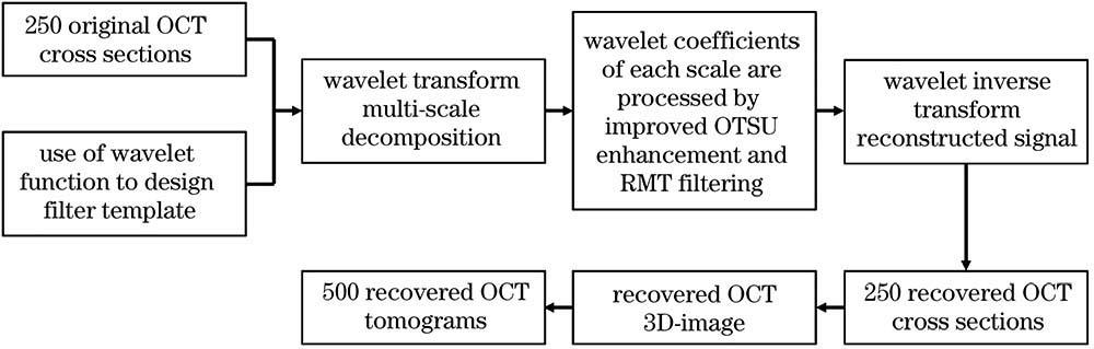
    Fig. 1. Algorithm flow diagram
    Rotating nuclear templates with different rotation angles. (a) 45°; (b) 30°; (c) 15°; (d) 0°; (e) 165°; (f) 150°; (g) 135°; (h) 120°; (i) 105°; (j) 90°; (k) 75°; (l) 60°
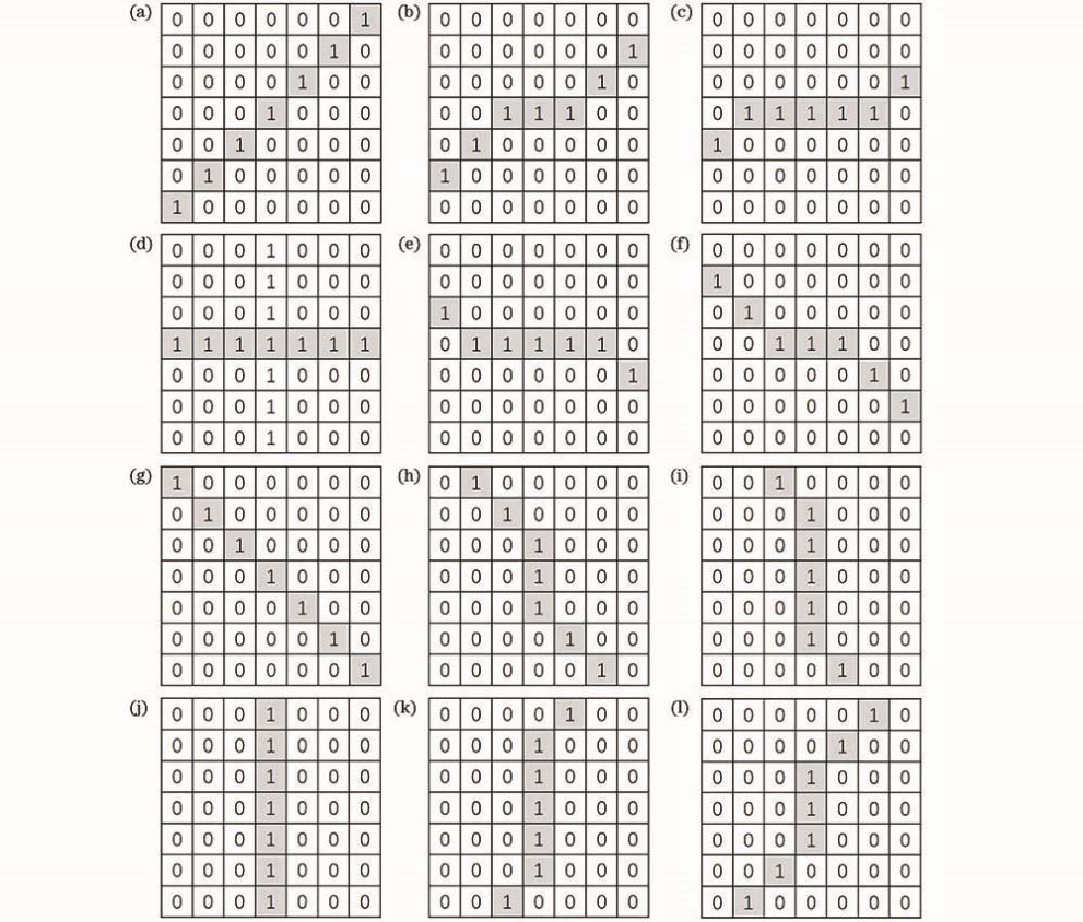
    Fig. 2. Rotating nuclear templates with different rotation angles. (a) 45°; (b) 30°; (c) 15°; (d) 0°; (e) 165°; (f) 150°; (g) 135°; (h) 120°; (i) 105°; (j) 90°; (k) 75°; (l) 60°
    Filter templates in horizontal direction under different rotation angles. (a) 135°; (b) 90°; (c) 45°; (d) retain center of rotation
    Fig. 3. Filter templates in horizontal direction under different rotation angles. (a) 135°; (b) 90°; (c) 45°; (d) retain center of rotation
    Filter templates in vertical direction under different rotation angles. (a) 135°; (b) 0°; (c) 45°; (d) retain center of rotation
    Fig. 4. Filter templates in vertical direction under different rotation angles. (a) 135°; (b) 0°; (c) 45°; (d) retain center of rotation
    Filter templates in diagonal direction under different rotation angles. (a) 0°; (b) 90°
    Fig. 5. Filter templates in diagonal direction under different rotation angles. (a) 0°; (b) 90°
    Decomposition and reconstruction process of secondary algorithm. (a) Original intracranial cortical blood vessel PT-OCT cross-sectional image; (b) PT-OCT cross-sectional image processed by proposed algorithm; (c) image after first-level wavelet decomposition; (d) after second-level wavelet decomposition image; (e) enhanced secondary low-frequency image; (f) filtered secondary horizontal detail image; (g) filtered secondary vertical detail image; (h) filtered secondary diagonal detail image; (i)
    Fig. 6. Decomposition and reconstruction process of secondary algorithm. (a) Original intracranial cortical blood vessel PT-OCT cross-sectional image; (b) PT-OCT cross-sectional image processed by proposed algorithm; (c) image after first-level wavelet decomposition; (d) after second-level wavelet decomposition image; (e) enhanced secondary low-frequency image; (f) filtered secondary horizontal detail image; (g) filtered secondary vertical detail image; (h) filtered secondary diagonal detail image; (i)
    Comparison of filtering results of 89th frame and 106th frame OCT cross-sectional images by different algorithms. (a) Effect of traditional RKT algorithm after processing 89th frame; (b) effect of improved RKT algorithm after processing 89th frame; (c) effect of traditional RKT algorithm after processing 106th frame; (d) effect of improved RKT algorithm after processing 106th frame
    Fig. 7. Comparison of filtering results of 89th frame and 106th frame OCT cross-sectional images by different algorithms. (a) Effect of traditional RKT algorithm after processing 89th frame; (b) effect of improved RKT algorithm after processing 89th frame; (c) effect of traditional RKT algorithm after processing 106th frame; (d) effect of improved RKT algorithm after processing 106th frame
    PT-OCT 3D image and its side view processed by different algorithms. (a) Unprocessed image; (b) traditional RKT algorithm; (c) improved RKT algorithm; (d) side view of Fig. (a); (e) side view of Fig. (b); (f) side view of Fig. (c)
    Fig. 8. PT-OCT 3D image and its side view processed by different algorithms. (a) Unprocessed image; (b) traditional RKT algorithm; (c) improved RKT algorithm; (d) side view of Fig. (a); (e) side view of Fig. (b); (f) side view of Fig. (c)
    Tomography images at different imaging depths. (a) 1.16mm; (b) 1.35mm; (c) 1.46mm; (d) 1.57mm; (e) 1.66mm; (f) 1.90mm; (g) 2.07mm
    Fig. 9. Tomography images at different imaging depths. (a) 1.16mm; (b) 1.35mm; (c) 1.46mm; (d) 1.57mm; (e) 1.66mm; (f) 1.90mm; (g) 2.07mm
    Parameter curves of filtered tomographic images at different depths. (a) RMSE; (b) PSNR
    Fig. 10. Parameter curves of filtered tomographic images at different depths. (a) RMSE; (b) PSNR
    ImageDenoising algorithmRRMSEPPSNR/dB
    89th frameTraditional RKT18.185535.5335
    Improved RKT34.891932.7036
    106th frameTraditional RKT10.271238.0146
    Improved RKT19.935435.1345
    Table 1. Comparison of objective parameters of different algorithms on OCT intracranial cortical blood vessel images
    Weiyuan Huang, Jiayi Wu, Hanhong Ren, Nanshou Wu, Bo Wei, Zhilie Tang. Rotating Kernel Transformation Denoising Algorithm Based on Wavelet Transform in Photothermal Optical Coherence Tomography[J]. Laser & Optoelectronics Progress, 2020, 57(22): 221005
    Download Citation