• Infrared and Laser Engineering
  • Vol. 51, Issue 2, 20210852 (2022)
Ningyan Xu1, Lu Chen2, Jing Huang1, Yutong Zou1, Qun Yuan1, and Zhishan Gao1
Author Affiliations
  • 1School of Electronic and Optical Engineering, Nanjing University of Science and Technology, Nanjing 210094, China
  • 2Northern Information Control Research Institute Group Co. Ltd, Nanjing 211153, China
  • show less
    DOI: 10.3788/IRLA20210852 Cite this Article
    Ningyan Xu, Lu Chen, Jing Huang, Yutong Zou, Qun Yuan, Zhishan Gao. Review of design methodology for starting-point of freeform surface imaging optical system[J]. Infrared and Laser Engineering, 2022, 51(2): 20210852 Copy Citation Text show less
    Different off-axis structures. (a) 4-type structure off-axis two-reflective system; (b) Z-type structure two-reflective system; (c)-(j) Eight structural types of off-axis three-reflective system
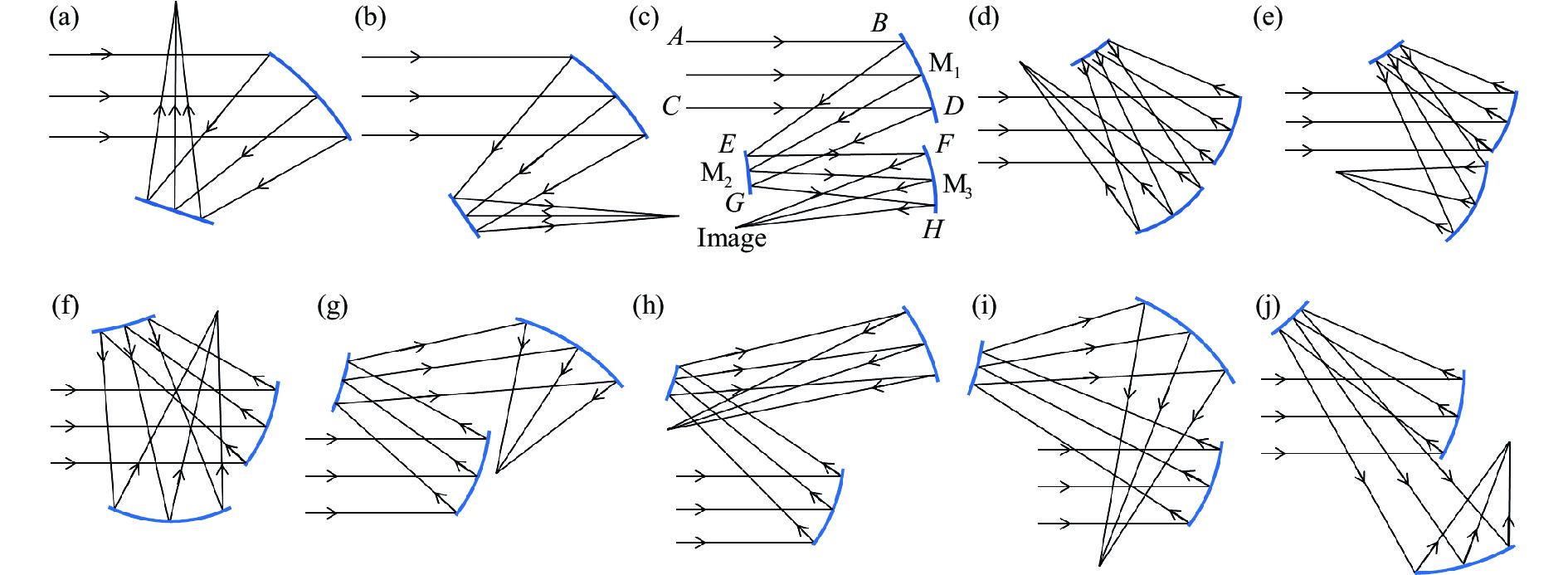
    Fig. 1. Different off-axis structures. (a) 4-type structure off-axis two-reflective system; (b) Z-type structure two-reflective system; (c)-(j) Eight structural types of off-axis three-reflective system
    Schematic of the principle of partial differential equation method
    Fig. 2. Schematic of the principle of partial differential equation method
    Schematic of the principle of SMS
    Fig. 3. Schematic of the principle of SMS
    Schematic of the principle of CI-2D[27]. (a) Initial structure; (b) Sampling feature rays; (c) Construction of surface and iteration; (d) Starting-point of freeform surface imaging optical system
    Fig. 4. Schematic of the principle of CI-2D[27]. (a) Initial structure; (b) Sampling feature rays; (c) Construction of surface and iteration; (d) Starting-point of freeform surface imaging optical system
    Schematic of expending FOV. (a) Expanding the FOV in the X; (b) Expanding the FOV in the Y
    Fig. 5. Schematic of expending FOV. (a) Expanding the FOV in the X; (b) Expanding the FOV in the Y
    Flow chart of alternate optimization method based on freeform surface
    Fig. 6. Flow chart of alternate optimization method based on freeform surface
    Optical path of ellipsoidal mirror system. (a) Single ellipsoid mirror; (b) Overlapping double ellipsoidal mirrors; (c) A head-mounted display system[37]
    Fig. 7. Optical path of ellipsoidal mirror system. (a) Single ellipsoid mirror; (b) Overlapping double ellipsoidal mirrors; (c) A head-mounted display system[37]
    Design of single reflector[38]
    Fig. 8. Design of single reflector[38]
    Design examples of fusion of parabolid. (a) Czerny-Turner imaging spectrometer[40]; (b) f-θ telecentric scanning system[41]
    Fig. 9. Design examples of fusion of parabolid. (a) Czerny-Turner imaging spectrometer[40]; (b) f-θ telecentric scanning system[41]
    Design steps of fusion of parabolid[42]. (a) Split FOV/aperture; (b) Solve parameter of sub-mirror of off-axis paraboloid; (c) Surface fusion
    Fig. 10. Design steps of fusion of parabolid[42]. (a) Split FOV/aperture; (b) Solve parameter of sub-mirror of off-axis paraboloid; (c) Surface fusion
    Ningyan Xu, Lu Chen, Jing Huang, Yutong Zou, Qun Yuan, Zhishan Gao. Review of design methodology for starting-point of freeform surface imaging optical system[J]. Infrared and Laser Engineering, 2022, 51(2): 20210852
    Download Citation