
Fu Bi, Dongliang Zhang, Lidan Lu, Lianqing Zhu. Latest Progress of Integrated Optical Gyroscopes Sensitive Unit[J]. Laser & Optoelectronics Progress, 2021, 58(7): 0700005
- Laser & Optoelectronics Progress
- Vol. 58, Issue 7, 0700005 (2021)
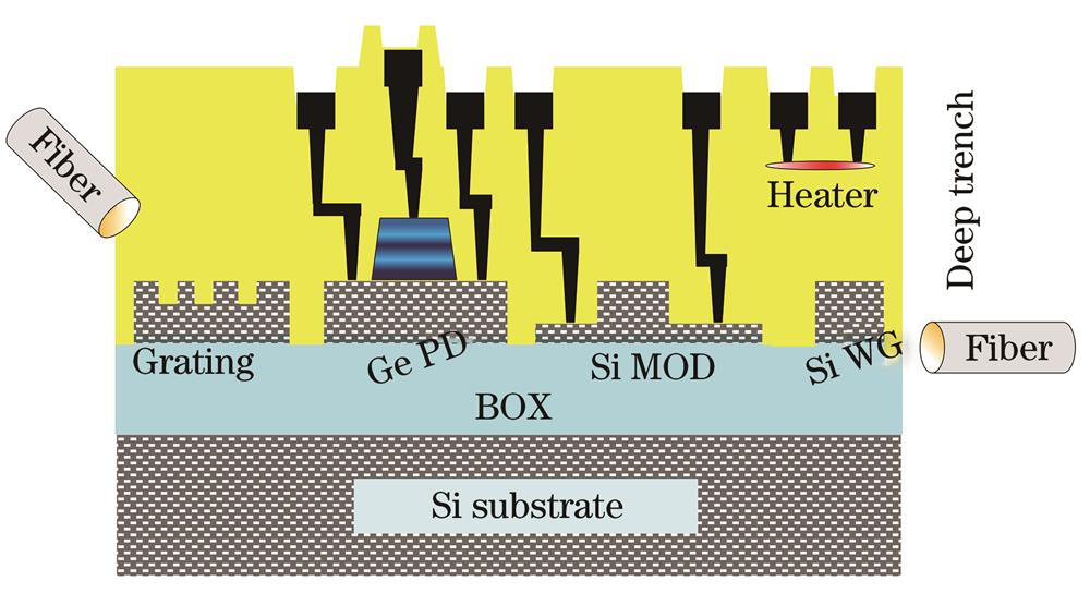
Fig. 1. Schematic diagram of SOI structure
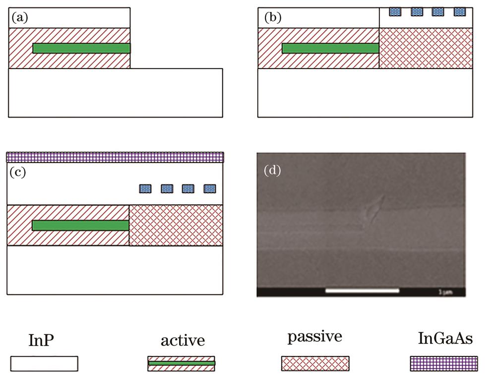
Fig. 2. Schematic diagram and SEM image of the end-face alignment process of InP-based photonic integration of active and passive structures. (a) Active thin film growth and structure etching on InP;(b) passive layer regrowth and grating patterning;(c) common top cladding growth;(d) SEM image
Fig. 3. InP optical waveguide resonator[17]. (a) InP optical waveguide resonant cavity structure; (b) low loss InGaAsP/InP ridge waveguide; (c) light field distribution at the tapered input; (d) light field distribution at tapered output
Fig. 4. Integrated optical gyroscope structural unit
Fig. 6. Two structural forms of resonant cavity. (a) Double runway resonant cavity structure[23];(b) resonant cavity structure with loss compensation[24]
Fig. 7. Gyroscope system composed of double resonant cavities[25]. (a) System structure diagram;(b) architecture of SiO2 dual-resonator
Fig. 8. Sketch map of transmissive resonator optic gyro based on silica-on-silicon waveguide[26]
Fig. 9. Configuration of triple-ring resonator configuration[28]
Fig. 10. Configuration of multi-ring resonant cavity[29]. (a) Three-dimensional model; (b) top view
Fig. 11. Schematic diagram of integrated optical structure based on two-dimensional photonic crystal[36]
Fig. 12. Micro-ring resonant cavity structure based on one-dimensional photonic crystal[37]
Fig. 13. Schematic diagram of multi-turn optical waveguide ring resonator[38]
Fig. 14. Schematic diagram of multi-turn optical waveguide resonator structure and gyroscope system structure[39]
Fig. 15. Schematic diagram of resonant cavity of mode-assisted gyroscope[40]. (a) Sensing element; (b) reference sensing element
Fig. 16. Resonant cavity with reciprocal sensitivity enhancement[41]. (a) Structure chart; (b) schematic diagram of alternating light path
Fig. 17. Design scheme of optical gyroscope based on a multi-gap surface plasmon waveguide[42]. (a) Structure chart; (b) cross section of multi-gap optical waveguide ring resonator
Fig. 18. Configuration of resonant cavity structure combined with MZI
Fig. 19. Schematic diagram of track-type ultrahigh-Q microcavity[47]. (a) Three-dimensional view;(b) top view
|
Table 1. Common polymer waveguide performance parameter[19]


Set citation alerts for the article
Please enter your email address

© Copyright 2018-2021 | Chinese Laser Press. All Rights Reserved 沪ICP备15018463号-20