• Laser & Optoelectronics Progress
  • Vol. 58, Issue 24, 2415001 (2021)
Zhe Huang1、*, Erjing Cheng1, Zhenyu Shao2, Wenyang Du2, Xuye Zhao2, and Qingde Yan1
Author Affiliations
  • 1School of Electronic Information and Automation, Tianjin University of Science and Technology, Tianjin 300222, China
  • 2Tianjin Hengdu Quantum Precision Instrument Technology Co., Ltd, Tianjin 300384, China
  • show less
    DOI: 10.3788/LOP202158.2415001 Cite this Article Set citation alerts
    Zhe Huang, Erjing Cheng, Zhenyu Shao, Wenyang Du, Xuye Zhao, Qingde Yan. Research on Guidance Method of Double Shield TBM Based on Monocular Vision[J]. Laser & Optoelectronics Progress, 2021, 58(24): 2415001 Copy Citation Text show less
    Definition of coordinate system of guidance system
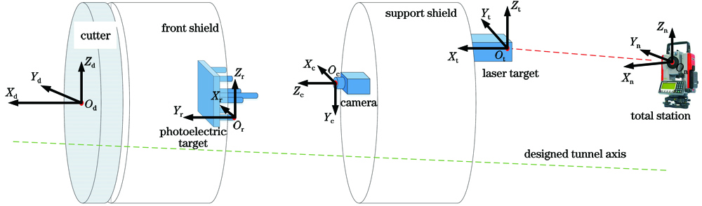
    Fig. 1. Definition of coordinate system of guidance system
    Principle diagram of deviation calculation
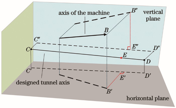
    Fig. 2. Principle diagram of deviation calculation
    Structure diagram of photoelectric target
    Fig. 3. Structure diagram of photoelectric target
    Recognition results of feature point
    Fig. 4. Recognition results of feature point
    Experimental environment for static repeatability measurement
    Fig. 5. Experimental environment for static repeatability measurement
    Experimental results of static repeatability measurement. (a) Horizontal bias; (b) vertical bias; (c) pitch angle; (d) roll angle; (e) yaw angle
    Fig. 6. Experimental results of static repeatability measurement. (a) Horizontal bias; (b) vertical bias; (c) pitch angle; (d) roll angle; (e) yaw angle
    Experimental environment for dynamic repeatability measurement
    Fig. 7. Experimental environment for dynamic repeatability measurement
    Experimental results of dynamic repeatability measurement. (a) Horizontal bias; (b) vertical bias; (c) pitch angle; (d) roll angle; (e) yaw angle
    Fig. 8. Experimental results of dynamic repeatability measurement. (a) Horizontal bias; (b) vertical bias; (c) pitch angle; (d) roll angle; (e) yaw angle
    Experimental environment for static measurement
    Fig. 9. Experimental environment for static measurement
    Schematic diagram of on-site installation
    Fig. 10. Schematic diagram of on-site installation
    No.X /mY /mZ /mDx /mmDy /mmDz /mm
    1P_camera12.93983.63431.3740-2.5-3.50.8
    P_TS12.94233.63781.3732
    2P_camera12.97063.62021.37621.9-4.6-2.4
    P_TS12.96873.62481.3786
    3P_camera13.23243.66581.3835-3.42.34.2
    P_TS13.23583.66351.3793
    4P_camera13.49823.60211.3753-2.74.4-0.1
    P_TS13.50093.59771.3754
    5P_camera14.05243.62031.3785-2.51.6-1.4
    P_TS14.05493.61871.3799
    6P_camera14.33264.75111.37414.7-2.1-2.2
    P_TS14.32794.75321.3763
    7P_camera14.56473.80171.3864-2.22.2-3.9
    P_TS14.56693.79951.3903
    8P_camera14.60893.66111.3883-1.94.00.1
    P_TS14.61083.65711.3882
    Table 1. Experimental data for static accuracy measurement
    Zhe Huang, Erjing Cheng, Zhenyu Shao, Wenyang Du, Xuye Zhao, Qingde Yan. Research on Guidance Method of Double Shield TBM Based on Monocular Vision[J]. Laser & Optoelectronics Progress, 2021, 58(24): 2415001
    Download Citation