
Yangyang Deng, Yuehui Wang, Yiqing Zhang, Axin Du, Jianguo Liu. The realization of a wide-angle voice transmission non-line-of-sight ultraviolet communication system[J]. Journal of Semiconductors, 2021, 42(9): 092301
- Journal of Semiconductors
- Vol. 42, Issue 9, 092301 (2021)
Abstract
1. Introduction
A non-line of sight (NLOS) ultraviolet (UV) scattering communication system has the advantage of anti-electromagnetic interference over the microwave communication system. The unique transform performance of ultraviolet photons in the atmosphere eliminates the need of rigorous alignment between the transmitter and the receiver, without which the line-of-sight infrared free space optical communication is nigh on impossible to achieve[
Early works in the 1960s chose a low-pressure mercury arc lamp or xenon flashtubes as the light source[
So far, research on the solar-blind UV communication system in theoretical and experimental regions has made great achievements, among which the theoretical analysis of the channel model[
Besides, there are a few articles focused on the realization of the NLOS UV communication system, and remarkable transmitting speed and outstanding communication distance are obtained. Wang et al.[
In this work, we design and realize a NLOS UV communication system using the direct modulation of LED arrays with the total size of 200 × 90 × 65 mm3 and an extra voice transform function is added. At the receiver side, a signal detecting and processing method based on Poisson distribution is introduced for counting the received UV photons. Field tests show that its transmission rate can reach to 300 kbps within 200 m, with a bit error rate (BER) below 0.88%. Besides, experiments on the relation between BER and deviation angle of the transmitter is carried out, and 10° deviation is allowed within the BER under 1.33%. The main contributions of this paper are as follows:
(1) We integrate the UV communication prototype into a carriable size, which is rare in the recent related designs. Thus, proved that UV communication system can take its great characteristic of no need for rigorous-alignment into practical usage.
(2) The wide deviation angle of the transmitter is applied to test the performance of this prototype. This is the first report to test the deviation angle property in such a long distance of 100 m, and a relatively high transmitting speed of 300 kbps.
(3) It is the first time it has been reported to have the NLOS UV communication prototype with voice transform function, which may bring inspiration to the usage scenarios of UV communication in the future.
2. Channel characterization
When the UV light emitted from the sun reaches the atmosphere, the solar-blind band around 200–300 nm will be strongly absorbed by the ozone layer, thus providing an extremely small background noise for the solar-blind UV communication. The solar-blind UV signal photons emitted from the transmitter will be scattered intensely by the aerosols and molecules floating in the air, which make it possible for the transmitter light to travel through blockages, thus realizing the communication link of NLOS scattering. Channel attenuation occurs during the spread of the photons, thus limiting the communication range to hundreds to thousands of meters, creating an effective communication region beyond which eavesdropping and interference are impossible to approach[
The state-of-the-art light emitting devices for building the NLOS UV system are LEDs and LDs. Due to the large path loss and channel attenuation mentioned above, the transmitted UV photons presents the faint characteristic at the detector’s photosensitive surface. To capture the photon-level signal, PMTs and APDs seem to become common choices for realizing the receiver side’s high sensitivity and gain.
When the signal photons traveled to the receiver side, the detected signal displays the character of discrete photoelectrons, whose number satisfies a Poisson distribution for the on–off keying (OOK) modulation scheme[
where
where
A photon counting module is added for the processing of synchronizing and judging the threshold of symbols. The synchronization sequences are added at the head of each transmitting frame, whose function is to evaluate the parameter
where
Based on the LLR information, we are able to improve the performance of judging the threshold photon numbers for information symbols, which will be applied in the later software procedure.
3. System design
3.1. The overall function
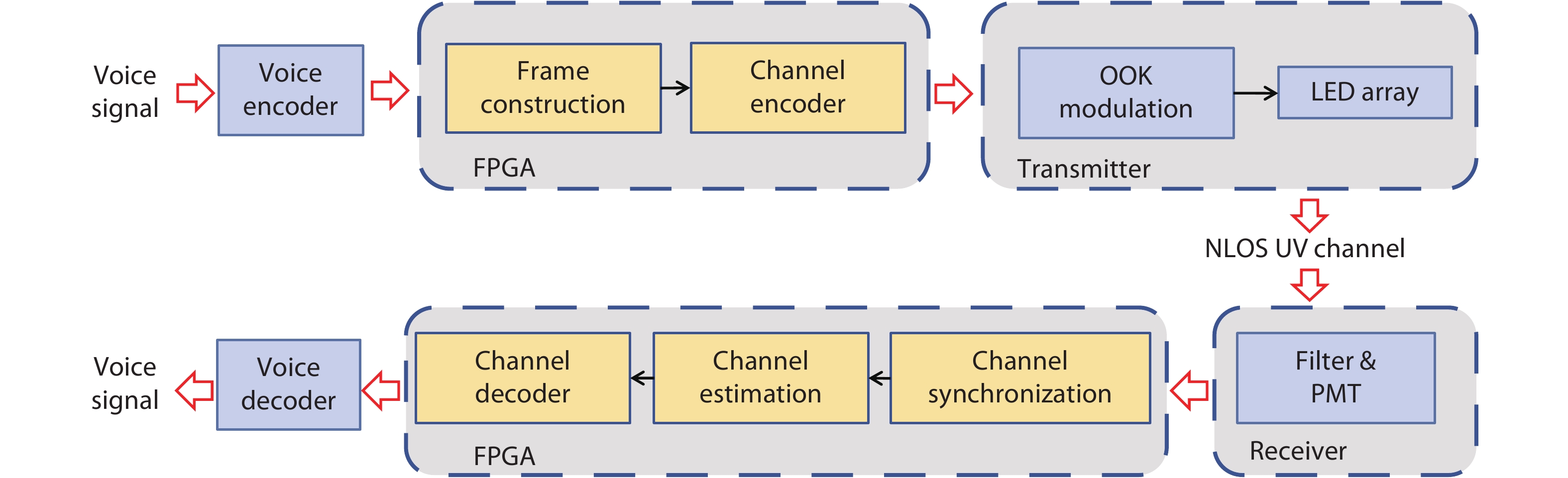
The work flow chart of the NLOS UV voice transforming communication system is depicted as Fig. 1. At the transmitter side, a voice codec is applied to collect the voice signals from the microphone and transform them into certain voice data formats. Then, the voice data is sent to the field programmable gate array (FPGA) for constructing the data frame where the adding of the synchronization sequences at the frame’s head and channel coding is proceeded. Then the coded data from the FPGA drives the transmitter in the modulation scheme of OOK.
![]()
Figure 1.(Color online) The work flow of voice transmission NLOS UV communication system at the transmitter and the receiver.
After the UV signals traveling through the atmosphere where scattering, reflection, and absorption of the particles in the air happened, one photon-level detector is applied to examine the UV photon signals at the receiver’s side, and the analog-to-digital converter (ADC) works here to transform the pulse output from the detector into digital signals which will be processed later. One FPGA is used here as the digital processing module, with the chip model of XC7K325T.
After the channel synchronization and estimation processing on the FPGA board, the information symbols are interpreted, including the frame definition and the transmitted data. The final voice data is then given to the voice codec, thus the speaker is playing the voice information.
3.2. The hardware implementation
To make the system more flexible in size, we use the LED array with the wavelength of 272 nm and total optical power of 40 mW. The collimating lens array of UV transparent are specially designed and set in front of the LED array to constrain the divergence angle to 40° according to the transmitting distance we preset. Use UC2708 as the driving chip, with a lifting time of 25 ns, and the driving signal outputs from the FPGA board.
Owing to the low optical power of the emitter and large path loss during the transmitting, the signal at the receiver presents the characteristic of discrete photons. At the receiver side, a solar-blind filter is applied in front of the PMT’s receiver window, blocking the background waveband, as its property shown in Fig. 2. The PMT we choose is the type H10720-113 made by Hamamatsu with a photosensitive diameter of 8 mm, responding to 185–700 nm. Besides, we designed a mechanical support for the PMT and its filter, and several rubber rings are set into the support’s groove in case of even a small account of background photons leaking or reflecting into the PMT. On the electrical processing, a two-stage transimpedance amplifier (TIA) circuit is designed using LTC6268-10 to further amplify the detected weak output signal of the PMT, with the gain of 100 kΩ. A differential operational amplifier of the type THS4509 is applied to convert the single-ended signal to a differential signal. A 120 Mbps sampling rate ADC of type ADS5463 is applied for the later digital processing.
![]()
Figure 2.The transmittance property of the filter, with the characteristics of band-pass from 256 to 280 nm, which is friendly to the communication band of 272 nm.
The final output voltage of a single photon of the receiver module differs each time due to the characteristic of PMT’s output, but generally higher than a certain value, which helps distinguish the signals from the background noise. In the system we design, the output of a single detected photon is above 200 mV after the amplifying circuit.
3.3. The software implementation
The output signal from the PMT when detecting a UV photon is shown in Fig. 3. When transmitting in the OOK modulation, the received waveform of the signal is shown as Fig. 4. A large difference lies here in the receiving waveform between the NLOS UV communication and the optical wireless communication. The signal detected by the PMT presents the discrete pulse pattern, the symbol 1 in the OOK modulation comprises dozens of pulses and the symbol 0 presents few pulses. Thus, it is vital to discern those pulse-signals into information symbols. The process of the photon signal we describe are all realized at the receiver’s FPGA board, where channel estimation and synchronization are carried out.
![]()
Figure 3.The output of PMT shows the pulse pattern when it captures one photon.
![]()
Figure 4.When the transmitter starts signaling, the typical waveform output by the receiver shows the background noise and pulse signal.
To realize the synchronization in the communication, a special sequence of 256 bit is added before the information bits for each transmitting frame, aiming to determine the beginning of the whole frame and to find the best synchronization position for each symbol, and customize the judging threshold of pulse numbers for the symbol 0/1. The design of the synchronization header is based on the M sequence, where the correlation calculation is carried out to find the correlation peak, thus the sequence is chosen as the synchronization sequence.
On the receiver’s side, pulse binarization, channel synchronization and estimation are processed in order. The received noise can be divided into two categories, optical noise from the sun’s background radiation and electrical noise from the TIA. Thus, each pulse detected may present a received UV photon or a relatively large noise output from the circuit. It is essential to eliminate noise and distract the signal pulses. A threshold value is set for the binarization on the process of the pulses, preliminary cutting out the small volume noises beneath the threshold. Thus, the value 1 may present a pulse generated by a UV photon signal or a relatively large noise output, while the value 0 indicates no signal pulses we desire. For the later synchronization procedure, we divide every symbol into several chips for the convenience of the digital processing, and a pulse counting unit is designed for accumulating the total pulses in a chip’s duration time. When the correlation value between the synchronization sequence and the total pulse numbers in one symbol’s duration time outnumber the threshold, it is judged that the header of the frame is found. Afterwards, the finding of the best synchronization location is set out by finding the maximum value of the cross-correlation in the length of the next dozen chips, thereby the synchronization is achieved here. Given the synchronization sequence, the receiver accumulates the total pulses standing for the symbol 0 or 1 respectively when it refers to the header’s sequence, thus the average pulses in symbol 0 or 1 can obtain for the transmitted data’s channel estimation. Let
Thus, the remaining transmitted data can be judged according to the threshold listed above.
4. Experimental results
We carried out an NLOS UV communication outfield test with clear weather and air humidity of 76% and air pressure of 1020 mbar, in the Institute of Semiconductors, Chinese Academy of Sciences. The test shows the background photons can reach up to (5–6) × 104 per second with such a sealing receiver structure as Fig. 5 shows.
![]()
Figure 5.Outfield test on the output waveform after the 2-stage TIA of the receiver under solar background radiation in a clear weather.
On the condition where there is no blockage standing between the two prototypes, the UV communication test at the distance of 200 m was carried out, with the transmitting rate of 300 kbps. The BER of the system reached to 0.88% in the distance of 200 m. While in the distance of 225 m, the BER increased to 1.51%. However, when the distance reached 235 m, the receiver failed to decode a small number of frames, with the BER of 5.98%. To explore the whole characteristic of this prototype, a 250 m distance test was carried out, but only a quarter of the whole sending data was decoded. Fig. 6 shows the waveform at the receiver’s side as the transmission distance changed from 200, 225, 235 and 250 m. It needs to be added that 4 units of ADC equals to 1 mV.
![]()
Figure 6.The waveform of the signal received on the ADC at the distance of (a) 200 m, (b) 225 m, (c) 235 m and (d) 250 m. With the increase of Tx and Rx distance, the number of photons received by the receiver decreases, resulting in the decrease of the number of pulses detected.
Besides, we set a test to find out the trends of BER and the deviation angle of the transmitter. 100 m lied between the transmitter and the receiver. Seen in Fig. 7, the BER shows no obvious rising or falling trend when the Tx deviation angle turning from –8° to +6°, and the BER fluctuates around 0.4%. It seems that under the angle of +8°, the result should be alike that of –8° as a result of symmetrical structure. However, it gets a 0.73% BER, which is most likely to be introduced by not having the 0° deviation in a straight direction. When it points to –10° and +10°, the BER reached to 1.33% and 1.25%, respectively. The BER increased intensely as the angle turned to more than ten degrees. When turning into –12° and +12°, the BER raised to 4.61% and 20.47% respectively, with 2.5% and 18.75% transmitting the missing frame. Such asymmetry BER results at the big angle may be introduced by the algorithm of counting the few UV photons, thus one photon level discrepancy can cause a big difference as the algorithm proceeding the data.
![]()
Figure 7.With the deviation of the transmitter’s transmission angle, the BER of the system increases.
Considering the angle deviation test, here are a few experimental results in other related works. In 2014’s work[
In the process of testing, for the detector’s sensitivity being a photon level, the received light power cannot be measured by the optical power meter. Instead, the average effective photon number of frame header symbol 1 measured by the UV photon counting program is concerned as the statistical standard of the received light intensity. We set an indoor experiment to find the relationship between the BER and the mean effective UV photon number of symbol 1 in the synchronization header, shown in Fig. 8. It can be deduced that the BER decreases intensely as the average effective UV photon number reach to tens and above.
![]()
Figure 8.With a higher average number of detected photons in symbol 1, the transmission performance reveals better property and a reduced BER.
5. Conclusion and discussion
A carriable NLOS UV communication system prototype with voice transform function is demonstrated here. Using the 272 nm LED array as the light source and a UV-sensitive PMT as a detector, we integrate the transceiver and digital processing circuit into one single prototype, with the total size of 200 × 90 × 65 mm3. This demonstration proved that NLOS UV communication system can be integrated into a carriable size, and the extra voice transmission function broadens the application scenarios for the NLOS UV communication. Further distance can be achieved with the rising of optical power.
Among all the UV light source, lasers are widely used for obtaining a desirable communication distance, with the advantage of high optical power and excellent collimation property, and the disadvantage of high-power consumption and bulky volume. LEDs otherwise, compared to UV lasers, have relatively lower optical power and worse collimation property. However, the need for low power consumption and the small volume make the LED the cardinal trend in the realization of a practical and flexible NLOS UV communication system. Besides, due to the limitation of the deep UV related devices such as a UV band pass filter and deep UV detector, the transmitting speed and distance of UV NLOS communication failed to meet some expectations. With the development of the UV devices, a higher-performance UV communication system can be pictured in the future. For later works, research on interactive connections and networking issues between the UV NLOS communication and modern communication methods can be expected.
Acknowledgements
This work was supported in part by the National Key R&D Program of China under Grant 2019YFB2203700, and in part by the National Nature Science Fund of China under Grants 61527820 and 61625504.
References
[1] A S Hamza, J S Deogun, D R Alexander. Classification framework for free space optical communication links and systems. IEEE Commun Surv Tutor, 21, 1346(2019).
[2] Z Y Xu, B M Sadler. Ultraviolet communications: Potential and state-of-the-art. IEEE Commun Mag, 46, 67(2008).
[3] A Vavoulas, H G Sandalidis, N D Chatzidiamantis et al. A survey on ultraviolet C-band (UV-C) communications. IEEE Commun Surv Tutor, 21, 2111(2019).
[4] Z Y Xu, H P Ding, B M Sadler et al. Analytical performance study of solar blind non-line-of-sight ultraviolet short-range communication links. Opt Lett, 33, 1860(2008).
[5] A Refaai, M Abaza, M S El-Mahallawy et al. Performance analysis of multiple NLOS UV communication cooperative relays over turbulent channels. Opt Express, 26, 19972(2018).
[6] L C Liao, Z N Li, T Lang et al. UV LED array based NLOS UV turbulence channel modeling and experimental verification. Opt Express, 23, 21825(2015).
[7] K K Garg, P K Singya, V Bhatia. ASER analysis of general order rectangular QAM for dual-hop NLOS UV communication system. 2019 National Conference on Communications (NCC), 1(2019).
[8] D F Zou, C Gong, K Wang et al. Characterization on practical photon counting receiver in optical scattering communication. IEEE Trans Commun, 67, 2203(2019).
[9] M L Wu, D H Han, X Zhang et al. Experimental research and comparison of LDPC and RS channel coding in ultraviolet communication systems. Opt Express, 22, 5422(2014).
[10] C Gong, K Wang, Z Y Xu et al. On full-duplex relaying for optical wireless scattering communication with on-off keying modulation. IEEE Trans Wirel Commun, 17, 2525(2018).
[11] C Gong, Q Gao, Z Y Xu. Signal detection for superposition transmission protocols for optical wireless scattering broadcast channel. IEEE Trans Wirel Commun, 17, 5480(2018).
[12] D F Zou, C Gong, Z Y Xu. Signal detection under short-interval sampling of continuous waveforms for optical wireless scattering communication. IEEE Trans Wirel Commun, 17, 3431(2018).
[13] S Arya, Y H Chung. Non-line-of-sight ultraviolet communication with receiver diversity in atmospheric turbulence. IEEE Photonics Technol Lett, 30, 895(2018).
[14] H P Ding, G Chen, A K Majumdar et al. Modeling of non-line-of-sight ultraviolet scattering channels for communication. IEEE J Sel Areas Commun, 27, 1535(2009).
[15] T Shan, J Ma, T Wu et al. Modeling of ultraviolet omni-directional multiple scattering channel based on Monte Carlo method. Opt Lett, 45, 5724(2020).
[16] S Hasan Hariq, N Odabasioglu. Spatial diversity techniques for non-line-of-sight ultraviolet communication systems over atmospheric turbulence channels. IET Optoelectron, 14, 327(2020).
[17] G C Wang, K Wang, C Gong et al. A 1 Mbps real-time NLOS UV scattering communication system with receiver diversity over 1km. IEEE Photonics J, 10, 1(2018).
[18] Z T Sun, L J Zhang, P A Li et al. 1 Mbps NLOS solar-blind ultraviolet communication system based on UV-LED array. Proc SPIE, 1061, 106170O(2018).
[19] X B Sun, Z Y Zhang, A Chaaban et al. 71-Mbit/s ultraviolet-B LED communication link based on 8-QAM-OFDM modulation. Opt Express, 25, 23267(2017).
[20] R Z Yuan, J S Ma. Review of ultraviolet non-line-of-sight communication. China Commun, 13, 63(2016).
[21] K Wang, C Gong, D F Zou et al. Demonstration of a 400 kbps real-time non-line-of-sight laser-based ultraviolet communication system over 500 m. Chin Opt Lett, 15, 040602(2017).


Set citation alerts for the article
Please enter your email address

© Copyright 2018-2021 | Chinese Laser Press. All Rights Reserved 沪ICP备15018463号-20