1School of Electronic and Communication, Shenzhen Institute of Information Technology, Shenzhen 518172, China
2State Key Laboratory of Information Photonics and Optical Communications, Beijing University of Posts and Telecommunications (BUPT), Beijing 100876, China
Xuemei Cao, Mingxiang Guan, Linzhong Xia, Xinzhu Sang, Zhidong Chen. High efficient generation of holographic stereograms based on wavefront recording plane[J]. Chinese Optics Letters, 2017, 15(12): 120901
Copy Citation Text
A computer generated holographic stereogram based on the wavefront recording plane (WRP) is presented. A WRP closed to the parallax image plane is introduced to record the complex amplitude in a small region for each point in the parallax image. By using three times of fast Fourier transform (FFT) to execute the Fresnel diffraction calculation between the WRP and the holographic stereogram plane, the object wave contributing to the hologram pattern can be achieved. The computation complexity of the proposed approach is dramatically reduced. The results show that the calculation time can be decreased by more than one order of magnitude.
Holography technology has attracted considerable attentions since it was first reported by Gabor[1–3]. For traditional optical holography, the holographic recording of a real object is performed by the interference of waves. An extreme stability of the optical system and a powerful, highly coherent laser source is required, which seriously restricts its application outside the laboratory. Numerous new holographic techniques for the incoherent illuminated three-dimensional (3D) scenes were reported. Multiple viewpoints projection (MVP) holography[4–6] and holographic stereograms[7–9] are two important approaches.
For conventional holographic stereograms[7], a hologram is divided spatially, and each captured parallax image is coherently recorded on part of the holographic film by moving a mask over the film. When the hologram film is illuminated by the same reference wave, the area recorded by the parallax image becomes the corresponding viewpoint. Subsequently, computer generated holographic stereograms-based parallax image calculation and diffraction calculation were performed developed[9–11]. A computer generated holographic stereogram is a combination of an optical holographic stereogram with a computer, which can record and reconstruct vivid 3D scenes of both virtual and real objects without requiring a highly stable coherent optical system, which attracted intense attention. Recently, a simplified calculation method for computer generated holographic stereograms based on conventional holographic stereograms from multi-view images was reported[12]. The holographic stereogram was obtained by adding all of the wavefronts converging to the viewpoints from the parallax images. Although the parallax images are arranged on the same plane, they cannot be directly converted into two-dimensional (2D) wavefronts based on fast Fourier transforms (FFTs). Because, the premise of the 2D wavefront calculation based on FFTs is that the pixel number of two 2D planes are the same. Since the pixel number of the parallax image is not the same as the hologram, the parallax image cannot be directly converted into 2D wavefronts based on FFTs. The complex amplitude of the parallax image should be recorded on the hologram point by point. Since the hologram is not divided spatially, and each point of the parallax images contributes to the entire hologram, the implementation of the calculation process is time consuming.
Some effective approaches for accelerating hologram calculation were proposed. Algorithms and hardware implementations for fast generation of computer holograms were reviewed[13,14]. The wavefront recording plane (WRP) technique was reported to accelerate the calculation of a computer generated hologram (CGH) which based on the ray tracing technique[15]. Different from traditional methods[16,17] aimed to enhance the generating efficiency of a hologram from an object, the WRP scheme converted the object information into a WRP that was placed closed to the object scene. The object wave emitted from each object point covered a small area on the WRP. By adding the contribution of an individual object point, the overall diffraction pattern on the WRP could be achieved. The implementation can proceed with a very small amount of calculation. The hologram can be easily acquired by Fresnel diffraction between the WRP and holographic plane. The WRP was successfully deployed for fast generation and processing of digital holograms[18–20].
Sign up for Chinese Optics Letters TOC. Get the latest issue of Chinese Optics Letters delivered right to you!Sign up now
Here, the WRP is applied into the generation of a holographic stereogram. An accelerated calculation scheme for the generation of holographic stereograms from a sequence of parallax images and the WRP is presented, and the calculation time can be greatly reduced by more than one order of magnitude.
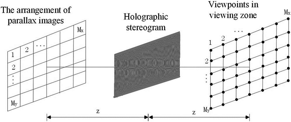
As shown in Fig. 1, 2D distributed viewpoints are considered to provide both horizontal and vertical parallaxes. represents the number of the viewpoints. is the distance between the holographic stereogram and the viewpoints.
Figure 1.Schematic diagram illustrating the arrangement of viewpoints in the viewing zone.
Figure 2 shows the generation process of the object wave. It illustrates that a wavefront corresponding to a parallax image converging to a viewpoint is considered. By adding the wavefronts of all of the parallax images, the whole object wave can be obtained, which can realize the 3D display from the holographic stereogram[21–23].
Figure 2.Object wave generated from sequential parallax images.
The algorithm to synthesize the object wave can be expressed as the following: where is the object point information of the parallax image. is the total number of pixels in the parallax image plane. indicates the random phase distribution added to the parallax image. It is used to enlarge the extent of the diffraction patterns of the parallax images to be comparable to the pitch of the viewpoints so that the light intensity distribution becomes uniform in the viewing zone. represents the wave number. is the wavelength of the illumination light. (, ) and (, ) denote the coordinates of the viewpoint and the holographic stereogram, respectively. The summation is performed for each point. Thus, to implement the calculation of Eq. (1) is time consuming. The holographic stereogram can be achieved by adding the reference wave to the object wave.
Compared Eq. (1) with the ray tracing algorithm[15] to synthesize the hologram, the WRP method can be used in the synthetic process for a holographic stereogram. Figure 3 is the schematic diagram of the proposed method. Between the parallax image plane and the holographic stereogram plane, a virtual plane WRP closed to the parallax image plane is introduced. The complex amplitude of each point on the parallax image is recorded in a small region on the WRP. After repeating the process for all of the points in the parallax images, the entire complex amplitude on the WRP can be acquired. Then, by executing the Fresnel diffraction calculation between the WRP and the holographic stereogram plane, the object wave contributing to holographic stereogram can be achieved.
Figure 3.Proposed method to generate the holographic stereogram.
According to the principle, the proposed method consists of two steps. First, the complex amplitude recorded on the WRP, can be expressed as where (, ) and (, ) are the coordinates of the point in the parallax image and WRP, respectively. is the intensity of the th point in the parallax image. indicates the distance between the parallax image plane and the WRP. The maximum diffraction angle and the distance contributed to controlling the region of the complex amplitude recorded on the WRP. When is small enough, the object light traverses small regions on the WRP. represents the recording region for the th point on the WRP. The length of a side on the rectangular region is , which can be expressed as[18]where p is the pixel pitch of the holographic stereogram.
Subsequently, the Fresnel diffraction computation between the WRP and the holographic stereogram plane is implemented. In order to avoid the sampling interval on the diffracted field variation, depending on the propagation distance, the convolution algorithm is adopted. Three times of FFT are used to accelerate the calculation in the process as follows: where is designated as the object wave contributing to the holographic stereogram. , and is the distance between the WRP and the holographic stereogram plane. and represent the Fourier transform and the inverse Fourier transform, respectively. Then, a reference wave is added to the object wave. and represent the amplitude and the phase angle of the reference wave, respectively. By controlling the phase angel of the reference light , an off-axis hologram pattern can be obtained. The conjugate image is separate from the reconstructed image. The holographic stereogram, which eliminates the zero-order diffraction light, can be expressed as the following equation:
The computation complexity of the original algorithm in Ref. [12] for the holographic stereogram expressed in Eq. (1) is . 2 indicates the calculations of the real and imaginary parts, and means the number of the arithmetic operations, such as addition and multiplication. is the resolution of the holographic stereogram.
By comparing it with Eq. (1), the amount of the computation from Eq. (2) is . and are the horizontal and vertical pixel sizes of the WRP, respectively. The computation complexity between the WRP and the holographic stereogram, including three FFTs, is . means the number of the arithmetic operations in one FFT operation. The calculation amount of this step is a constant. Hence, the total computation complexity of the proposed method is . If is large enough, the total computation complexity can be approximated as . When the parallax image is close to the WRP, is much smaller than . Therefore, the calculation complexity of the proposed method is much smaller than that of the original synthetic approach.
In order to synthesize the holographic stereogram, the parallax images should be acquired first. Various technologies of capturing multiple images of objects were developed[24,25]. In our implementation, parallax images for 18 viewpoints are considered. In order to verify the validity of the generated viewpoints with the proposed method, images with number characters are first used instead of the real parallax images. The resolution of the parallax images is . The distances are and , respectively. The range of distance is . is just a value we adopted to verify the effectiveness of the proposed method. If , the calculation time will be decreased. If , the calculation time will be increased correspondingly, but less than the calculation time without using the WRP.
The wavelength is set to be . The resolution of the holographic stereogram is , and the pixel pitch is . The sampling theorem provides the wide of the entire view zone, which is . In order to minimize the crosstalk between the viewpoints, the pixel pitch of the parallax image is set to and . Thus, the view zone of the individual viewpoint is in the horizontal, and in the vertical. To implement the Fresnel diffraction between the WRP and holographic stereogram plane, the resolution of the WRP should be the same as the holographic stereogram. The pixel size of the WRP is set to be either or . In order to obtain sharp reconstructed images, a uniform phase distribution is chosen as the phase distribution . Figure 4 shows the generated holographic stereogram. Figures 4(a) and 4(b) are the amplitude and the phase of the object wave, respectively. Figure 4(c) is the generated holographic stereogram by adding the reference.
The phase angel of the reference light is set to be 2°. When the holographic stereogram is illuminated by the conjugate reference wave , the corresponding viewpoints can be obtained. In the numeric simulation, the ray tracing method is applied as the numerical reconstruction algorithm to obtain different views with different propagation directions. The reconstruction perpendicular distance is set to be , which is the same as the distance between the parallax image plane and the holographic stereogram. Figure 5 shows the numeric reconstructed results at different viewpoints with different numeric characters, which verifies the correction of the proposed method. Comparing Fig. 5 with the reconstructed results shown in Ref. [12], the image quality is roughly equal.
Figure 5.Different numeric characters generated at different viewpoints with the proposed method.
Then, 18 helicopter parallax images generated by the computer are used. One of the helicopter parallax images is shown in Fig. 6. The white line represents the road below the helicopter. The square in the right side represents a house, and the square in the left side is part of a tank. The white line and the squares are used as the background to facilitate the observation of the parallax. The numeric reconstructed images at different viewpoints are shown in Fig. 7. Small parallax, depending on different viewpoints, can be seen.
In the synthetic process of the holographic stereogram, an Intel Xeon X3430 2.4 GHz processor is used as a CPU. Time used to synthesize the holographic stereogram is listed in Table 1, which shows that the calculation time of the proposed method can be decreased by more than one order of magnitude. To further accelerate the calculation process, parallel operation of the GPU can be used[26].
Time (s)
Different Parallax Images
Method in Ref. [12]
Proposed Method
Numeric images
32544
1630
Helicopter images
32828
2166
Table 1. Time Contrast to Synthesize the Holographic Stereogram
In conclusion, an accelerated method to synthesize the computer generated holographic stereogram from sequence parallax images based on WRP is presented. By introducing a WRP close to the parallax image plane, the complex amplitude of each point in the parallax image can be recorded on a small region in the WRP. The diffraction calculation between the WRP and the holographic stereogram is implemented by three times of FFT. Compared with the referenced algorithm, the computation complexity of the proposed approach can be dramatically reduced. The results show that the calculation time can be decreased by more than one order of magnitude.
References
[1] Y. Zhang, J. Liu, X. Li, Y. Wang. Chin. Opt. Lett., 14, 030901(2016).
[2] Y. Li, Q. Li, J. Hu, Y. Zhao. Chin. Opt. Lett., 13, S11101(2015).
[3] J. Leng, X. Sang, B. Yan. Chin. Opt. Lett., 12, 040301(2014).