3D imaging techniques such as computed tomography, ultrasonography, and magnetic resonance imaging usually combine many scans computationally. Here, we report a 3D imaging approach using an optical-laser diffraction microscope with two different wavelength lasers in the same orientation. A double-layered sample constructed of silica spheres is used for coherent diffraction imaging with two lasers at 543 and 432 nm. The diffraction patterns obtained using a planar detector at a high numerical aperture are projected onto the Ewald spheres. 3D images of the double-layered sample are successfully reconstructed from the two-color spherical diffraction patterns.
Pursuing a high spatial and temporal resolution is critically important to investigating 3D structures and dynamics in material science, physics, and biology[1–4]. However, 3D reconstruction of objects usually requires a series of projections at different angles, depths, overlapped positions, or a large number of copies[5–7]. It is a challenging task to study the dynamic 3D imaging by conventional methods, especially for biological cells in their natural state and nanoparticles[8], which are easily damaged by high-energy radiation[9]. Recently, a novel single-orientation 3D imaging technique based on coherent diffraction imaging (CDI)[10] has been developed to surpass the challenges[11]. An algorithmic reconstruction of 3D imaging of objects can be obtained from Ewald spherical shells, which is derived from the measured 2D diffraction patterns on a planar CCD detector. Previous studies have demonstrated the 3D imaging of objects using soft X-ray and optical lasers[11–13]. Although some progress has been made, the 3D imaging method still faces challenges in imaging of large or thick objects due to limited information in reciprocal space, which also caused some arguments[14,15]. Recently, a sparsity-based approach has been attracted to recover the 3D molecular structures[16]. Some researchers proposed volume optics, which is designed by a volumetric scattering approach based on the concept of an Ewald sphere[17]. In spite of these methods to recover the 3D images of objects, multiwavelength diffraction patterns provide more information to improve the convergence speed during reconstructions and enhance the quality of coherent imaging. This strategy is easily realized with energy-resolved detectors for optical laser microscopy, even for X-ray free electron laser (XFEL) diffraction imaging[18]. With the development of multiwavelength XFEL[19], new methods based on diffraction imaging become essential.
In this Letter, we experimentally demonstrated for the first time an approach to recover the 3D image of an object using two Ewald spheres with high numerical apertures. The result indicates that utilizing multiple-wavelength laser sources for deciphering the 3D image of materials has potential applications in single-orientation measurement.
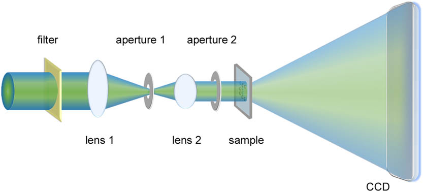
A general schematic diagram for the imaging of 3D objects is shown in Fig. 1. The experiment was carried out using a laser diffraction microscope with two lasers in the same orientation. The intensity of the laser beams was attenuated by neutral density filters and then passed through two convergence lenses with focal lengths of 1500 and 500 mm. The attenuation coefficient of a neutral density filter depends on the power of the laser used. The beam illuminated on the sample ensures a planar wavefront. Two apertures were positioned behind the lens to eliminate unwanted scattering of laser beams. To acquire light scattering from objects, we used a liquid nitrogen-cooled CCD detector with a pixel size of and a pixel array. A beamstop made of opaque materials with a size of was placed in front of the CCD detector to block the direct beam. In our diffraction experiment, a sample of silica spheres with diameters of was prepared on the two sides of a 30 nm thick membrane. As shown in Fig. 2, the silica spheres arranged on the one side in the form of the letter “C” and the other side in the form of the letter “T.” This arrangement forms a 3D architecture for laser diffraction with a dimension of about .
Sign up for Chinese Optics Letters TOC. Get the latest issue of Chinese Optics Letters delivered right to you!Sign up now
Figure 1.Schematic diagram of a coherent diffraction microscope with two lasers at 543 (green) and 432 nm (blue) in the same orientation.
Figure 2.Optical image of double-layered silica spheres on a 30 nm thick membrane. The silica spheres were arranged in the form of (a) “C” and (b) “T” (b) on two sides of the membrane. The yellow arrows indicate spheres on the other side of the membrane. Scale bar, 10 μm.
The first set of diffraction patterns was measured using a He–Ne green laser at 543 nm (1 mW). To acquire high spatial resolution diffraction patterns, the CCD detector was placed 37.5 mm from the sample, and a shutter was positioned in front of the sample. The beamstop was moved from the first quadrant to the third quadrant to eliminate the obscured data during the experiment. To further enhance the longitudinal resolution, the CCD detector was positioned at a higher diffraction angle to collect the signals from the sample. All the diffraction patterns at the same distance from the sample were tiled together and formed a high-spatial resolution pattern. However, the central missing data of the diffraction pattern was very large due to the beamstop, which was just in front of the CCD. Thus, in order to reduce the missing data, the CCD was moved to 132 mm from the sample to acquire more low-angle diffraction data. At each position, two sets of diffraction patterns were measured with the sample in and out (background) of the optical path. The acquisition time for each diffraction pattern was 1 s/exposure with 300 exposures, but for the background it was 1 s/exposure with 100 exposures. Then a blue laser at 432 nm with a power of 10 mW was moved into the optical path to measure the second set of diffraction patterns. After adjusting the attenuation coefficient of the neutral density filter and optimizing the beam path, the diffraction signals were acquired by the CCD detector at the same distance (37.5 mm) from the sample. To capture the central speckle of the diffraction patterns, the CCD detector was positioned at 202 mm from the sample, which is a little farther than that of the green laser beam.
The set of diffraction patterns measured with the same laser, such as the green laser, including the high and low spatial resolution diffraction patterns after background subtraction, were merged together to form a whole pattern of pixels with a small missing center and a high numerical aperture. To enhance the signal to noise ratio, the diffraction pattern was binned to a array by integrating pixels into 1 pixel, which was followed by deconvolution[20]. Figures 3(a) and 3(b) show the diffraction patterns performed with the green and blue lasers, respectively. Both the diffraction patterns at 543 and 432 nm were obtained at high numerical apertures[21,22]. As shown in Figs. 3(c) and 3(d), the low spatial frequency regions of the corresponding diffraction patterns [Figs. 3(a) and 3(b)] indicate that the missing centers are confined within the central speckles.
Figure 3.Experimental 2D diffraction patterns of the double-layered sample measured with the (a) green and (b) blue lasers. (c,d) The low spatial frequency regions of diffraction patterns (a,b) show that the missing intensity data are confined within the central speckles.
It has been known that the intensities of the far-field diffraction pattern, which are directly related to the modulus of a Fourier transform of the specimen’s electron density, can be described by[11]where is the reciprocal wave vector and is the finite object with a 3D structure. As for an oversampled diffraction pattern with a high diffraction angle, the degree of oversampling at higher angles is different from that of low angles, which results in a measurable distortion of the diffraction pattern on the planar CCD. To obtain linear oversampling and remove the distortion, one has to interpolate the diffraction pattern from a plane onto a spherical surface. According to the Laue equation expressed as the radius of the Ewald sphere is inversely proportional to the wavelength. Using the distance from the sample to the CCD and the CCD pixel size, the assembled planar diffraction patterns can be normalized and then projected onto the surface of the Ewald spheres on a 3D Cartesian grid[12]. Figures 4(a) and 4(b) show front views of the oversampled diffraction patterns on the Ewald spheres with the blue and green lasers in reciprocal space. Due to light diffraction, scattering and absorption by the phase object, the diffraction pattern is noncentrosymmetric. The shell matrix of the Ewald sphere is for the blue laser at 432 nm. Because the Ewald sphere is determined by the size and orientation of the incident wave vector, distinct spheres can exist for different illumination conditions. The two different wave data sets did not carried out reconstruction independently. Instead, we inserted the blue and green Ewald spheres into a 3D Cartesian grid and cropped it to contain effective diffracted signals from the sample. A 3D view of the spherical diffraction patterns for the two wavelengths in reciprocal space is shown in Fig. 4(c).
Figure 4.Front view of the oversampled diffraction patterns on the Ewald spheres with the (a) blue and (b) green lasers. (c) The spherical diffraction patterns for two input wavelengths on a 3D Cartesian grid. (d) A schematic of the cross section of the diffraction patterns projected on the Ewald spheres for the green and blue lasers.
For the 3D single-orientation diffraction imaging method, sufficient diffraction intensities with a large oversampling degree is crucial, especially for phase objects. Under a condition of multiple incident waves at the same orientation, varying the illumination wavelength changes the radius of the Ewald sphere, at the same time shifting the center of the sphere away from the reciprocal space origin. As shown in Fig. 4(d), a schematic diagram of the cross section of the two color Ewald spheres indicates that they have the same origin ( and are the centers of the blue and green Ewald spheres). Although the diffraction pattern of the sample is noncentrosymmetric, the two-color Ewald spheres provide more diffraction information for 3D reconstruction.
To obtain a 3D image of the double-layered sample, reconstruction from the 3D spherical diffraction pattern was subsequently carried out using an iterative hybrid input-output (HIO) algorithm. To make the reconstruction more efficient in reciprocal space, the Fourier magnitudes on the Ewald spheres remained the initial values in each iteration; and in real space, the voxel values outside a support that is defined for the image were slowly pushed close to zero. Additionally, the support was updated dynamically based on the shrink wrap algorithm[23]. After 5000 iterations, the reconstructed sample was shrunk to a columnar object from which an updated support was determined. After 1000 additional iterations, a final 3D image of the sample was achieved. For the 3D reconstruction of single-orientation imaging by multiple wavelengths, the image resolution is determined by the radius of the Ewald sphere and the diffraction angle. In this experiment, the shorter wavelength corresponds to the higher spatial frequency pattern (blue Ewald sphere), which determined the maximum spatial resolution achieved. For the diffraction pattern with the blue laser (432 nm), the scattering angle was about 36.7°. Thus, the transverse and the longitudinal resolutions were calculated to be 0.72 μm and 2.2 μm, respectively, according to the equations and [11].
To further analyze the amplitude reconstructions, the central slices of the spheres in the front “C” and back “T” layers were shown in Figs. 5(c) and 5(d), respectively. The regions with relatively low intensities (labeled by blue dashed circles) represent the overlapped area of the two spheres that are perpendicular to the beam direction. This is due to both the scattering and absorption of the silica spheres, which is also consistent with the architecture of the sample.
Figure 5.(a,b) 3D image (amplitude and phase) of the double-layered sample reconstructed from the diffraction patterns shown in Fig. 3. The central reconstructed slices of the spheres in (c) the front “C” and (d) back “T” layers. The blue dashed circles indicate the regions with a relatively low intensity due to the overlapped area of the two spheres perpendicular to beam direction.
In conclusion, we demonstrate successfully the 3D imaging of the double-layered silica spheres by constructing two Ewald spheres with two lasers at 543 and 432 nm. The morphology of the double-layered sample is clearly identified. Additionally, the amplitude changes in the overlapped spheres due to the absorption and scattering of light by the samples are observed. This method can be extended to multiple wavelengths to scan the reciprocal space for 3D imaging. Currently, the time resolution is still low due to the intensity of the lasers, the dynamic range, and the size of the CCD detector. However, with the maturation of multiwavelength XFEL technology and the development of high-speed energy-resolved detectors, 3D imaging based on single-orientation measurement has potential applications to the investigation of the 3D dynamic behavior of materials.
[9] R. Xu, H. Jiang, C. Song, J. A. Rodriguez, Z. Huang, C.-C. Chen, D. Nam, J. Park, M. Gallagher-Jones, S. Kim, S. Kim, A. Suzuki, Y. Takayama, T. Oroguchi, Y. Takahashi, J. Fan, Y. Zou, T. Hatsui, Y. Inubushi, T. Kameshima, K. Yonekura, K. Tono, T. Togashi, T. Sato, M. Yamamoto, M. Nakasako, M. Yabashi, T. Ishikawa, J. Miao. Nat. Commun., 5, 4061(2014).