Constantinos Valagiannopoulos, Vassilios Kovanis, "Engineering the emission of laser arrays to nullify the jamming from passive obstacles," Photonics Res. 6, A43 (2018)
Copy Citation Text
Non-Hermitian characteristics accompany any photonic device incorporating spatial domains of gain and loss. In this work, a one-dimensional beam-forming array playing the role of the active part is disturbed from the scattering losses produced by an obstacle in its vicinity. It is found that the placement of the radiating elements leading to perfect beam shaping is practically not affected by the presence of that jammer. A trial-and-error inverse technique of identifying the features of the obstacle is presented based on the difference between the beam target pattern and the actual one. Such a difference is an analytic function of the position, size, and texture of the object, empowering the designer to find the feeding fields for the lasers giving a perfect beam forming. In this way, an optimal beam-shaping equilibrium is re-established by effectively cloaking the object and nullifying its jamming effect.
Collective operation of laser waveguides in arrays and networks is the backbone of several state-of-the-art applications and recent advances in photonics and lightwave technologies. One-dimensional laser phased arrays characterized by strong nonlinearity and non-Hermiticity have been experimentally investigated in Ref. [1], where the effect of various symmetries on multimode emission and edge-mode lasing has been identified (free-space wavelength μ). In two dimensions, networks of optical nanoantennas have been found able to support functionalities beyond conventional focusing and steering useful in three-dimensional holography and biomedical testing [2] (μ). Of course, the major application of such structures remains efficient beam shaping, which can be electronically controlled based on hybrid prototypes of dielectric waveguides and metallic nanoemitters [3] (μ) and provides grating lobe-free steering for light detection and ranging [4] (μ).
Regarding beam forming in similar THz applications, an inverse problem for the excitations of an array of emitters has been lately formulated [5]. Inspired by long established level-set methods for computing moving fronts [6], new limits for the radiation of emitters [7] and the recent inverse-design paradigm shift in photonic design [8], the optimal arrangement of the cavity lasers is considered. It has been reported [5] that the distance between two consecutive radiating elements should fall within an approximate value range, so that the aggregate far-field response mimics perfectly a specific target pattern. In particular, it is found that the waveguides should not be placed too close to each other, or they will act as one source unable to create a directive collective pattern. Additionally, they cannot be very distant from each other because each emitter should talk with the neighboring ones to give a combined response instead of a sum of isolated and uncorrelated radiation patterns.
Forward and inverse problems such as the aforementioned ones have appeared for various bands of operational frequencies. In radio engineering, e.g., clusters of radiators have been traditionally used for optimal beam forming and, most importantly, adaptive techniques are employed to avoid the jamming of the collective radiation pattern due to several causes. Indicatively, signal processing methods that allow the system to fully adapt to a complex spatio-temporal environment containing jammers are presented in Ref. [9]. Furthermore, filtering techniques that suppress the perturbation of the information signal from interference sources by selecting the suitable transmitting array [10] or alleviate the harming effects of array imperfections [11] are also known and available. Alternatives to these historical signal cancellation [12] approaches are the modern cloaking techniques that allow an object to interact minimally with the background field. Similarly, the jamming effect of an obstacle can be mitigated with use of passive dielectric coats [13,14] or periodic metallic flanges that guide the incident field around it [15]. More easily, an object that jams the signal from the source can vanish by neutralizing its scattering field with active components such as electric/magnetic currents [16] or non-foster metasurfaces [17].
Sign up for Photonics Research TOC. Get the latest issue of Photonics Research delivered right to you!Sign up now
In this paper, we pair the structure of a beam-shaping laser array with a near-field obstacle that jams the formed radiation pattern. The cluster of emitters is identical to that of Ref. [5], where their optimal excitations for the best beam forming are computed. In the presence of the obstacle, the new effective current feeds leading to a perfect result are determined by solving the corresponding boundary value problem. The permissible range for the distance between the laser waveguides remains the same as in the obstacle-free analysis [5], since the object is passive and acts as a secondary source. The considered system combines gain (lasers) with loss (obstacle) and clearly constitutes a non-Hermitian photonic configuration [18–23]. Note that losses are not referring only to that part of energy that is converted into thermal form due to the passivity of the obstacle; we can define effective scattering losses describing the jamming created by the object that destroys an already established equilibrium. More specifically, in a working beam-forming device, an object appears and harms the proper response, behaving as an effective lossy part; to remedy that situation, we re-adjust the active part and cloak the obstacle by producing an aggregate response identical to the desired target pattern.
This paper is organized as follows. In Section 2, we present the configuration and state the assumption for the two-dimensional variation. To this end, we rigorously impose the boundary conditions to obtain a linear system whose solution is the local output fields of the lasers giving an optimal beam forming in the presence of the obstacle. In Section 3, we define the value ranges for the input parameters and our basic observable metric, which is the error of the obstacle-free solution. Furthermore, we present the possibility of finding some (or even all) objects’ features from the variations of that metric and demonstrate the effectiveness of our method if one has exact knowledge of the size, the texture, and the position of the obstacle. Finally, in Section 4, we summarize the proposed methodology and briefly mention our future plans on non-Hermitian engineering for structures of the same class.
2. PROBLEM STATEMENT
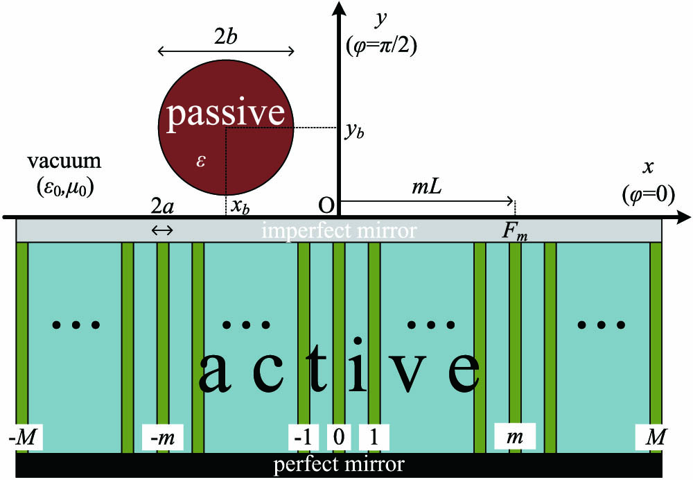
Let us consider an array of multiple laser emitters radiating into free space as that depicted in Fig. 1, where the used Cartesian and cylindrical coordinate systems are also defined. Referring to the plane, we regard laser waveguides of common finite length along axis defined by a perfect and an imperfect mirror (at ) and equispaced along axis. These cavities are properly fed to develop a -polarized electric field at their ends, with complex phasors denoted by for , which gets diffused into vacuum half space [24]. A cylindrical obstacle of radius and filled with material of relative complex permittivity , is positioned along axis and jams the collectively produced field of the waveguides [15]. We assume that the output fields do not significantly alter in the presence of the obstacle, despite the formed external cavity, which may influence the intrinsic behavior of the lasers. Indeed, the size of the cylinder is usually chosen much smaller than the length of the radiating aperture and thus may affect only a minute number of elements. Furthermore, according to feedback literature [25,26], there are ways to mitigate the effect of outer mirrors on the characteristics (intensity threshold) of the formed external cavity laser. The distance between two consecutive cavities equals , and the transversal size of each of them equals 2. The suppressed time dependence is of harmonic form: .
Figure 1.Schematic of the regarded configuration. The aggregate field of an active laser array is perturbed by a passive cylindrical obstacle.
A major assumption of this study is that the phasor of the electric field remains constant across the entire zone equal to ; it simplifies substantially the considered problem by making it two dimensional (field distributions independent from ). In other words, the structure and excitation are taken unaltered along axis and, thus, the system’s response is the same regardless of the observation plane, as long as it is parallel to the one. Such a reduction is not unrealistic, since one may consider identical (with respect to structure, texture, and feed) sets of waveguides as those existing on plane to be positioned along parallel planes covering a distance along axis equal to . In this way, an illusion of independence is created, which gets more successful for increasing . In particular, our analysis would be exactly valid for the entire space if and would describe qualitatively the spatial distributions only for plane for .
The background (-directed) electric field, in the absence of the obstacle, is written as an aggregation of the outputs of the emitters [5] where is the free-space wavenumber, and is the Hankel function of -th order and second type. The quantity is the free-space wavelength. The quantity is used for normalization purposes, since the outputs of the lasers are considered as constant throughout the cross section of the ends of the waveguides. Therefore, Eq. (1) is suitable only for points external to the laser cavities, since there is no actual field singularity in the interior of them. In other words, we assume that the waves are the outcome of point sources only outside of the lasers that produce them. This field is scattered by the obstacle, and the signal that perturbs the background distribution can be expressed as where is the cylindrical coordinate system centralized along the axis of the cylindrical scatterer and unknown complex coefficients for . The number is chosen large enough for the sum of Eq. (2) to converge; presumably, should be higher for optically larger obstacles.
By imposing the necessary boundary conditions [27] around the circular interface , one can determine the parameters as follows: where for , and is the Bessel function of -th order. The notations and for correspond to the positions of the radiating apertures of the laser waveguides at expressed in the obstacle’s coordinate system . The symbol is used for the wavenumber into the cylinder. Obviously, all the coefficients vanish for and for , since in both the aforementioned cases, the obstacle is absent [28]. In addition, the response from the cylinder is apparently proportional to the strength of the background field as created by the primary sources. The formula of the total -polarized electric field , expressed in the cylindrical coordinate system , is written for the far region as [29], where the polar (azimuthally dependent) profile is given by It is clear that is comprised of a part attributed to the background free-space radiation of the active sources and another part expressing the scattering effect of the passive obstacle on the far field. In this way, a significant component of the wave interactions between the obstacle and emitters is captured in spite of our assumption that the primary fields remain unaltered.
If one aims at imitating a far-field pattern by properly exciting the laser cavities that, in turn, produce the output local fields for , the equality should be ideally fulfilled for all the angles of the upper half space . In order to find the sets of complex quantities that optimally verify such a constraint, we use the following reasoning. Since the active part of is expressed as a finite sum of the basis functions: , let us project the exact equality of the far fields on the conjugate set of same-basis functions, namely, adopt the Galerkin [30] approach (where the testing functions are complex conjugates of the basis functions). In this sense, we act on with the operator for , and we obtain the linear system with an unknown optimal vector of fields . The matrix is the sum of two matrices: one representing the background field of the diffused waveguide outputs and another regarding the scattering field by the cylinder. The elements of the first matrix are analytically evaluated as Bessel functions of zeroth order, namely as indicated in Ref. [5]. The elements of the second matrix are given by where for are complex quantities computed via numerical integration. The elements of the constant vector express the projection of the target pattern on the testing functions, namely for .
The solution of the linear system will give the output fields of the active emitters making a radiation pattern that mimics optimally the ideal response in the presence of the obstacle with characteristics .
3. NUMERICAL RESULTS AND DISCUSSION
A. General Comments
In Ref. [5], the same problem is addressed but in the absence of the obstacle; only the emitters were radiating into free space. It has been found that for a target pattern whose maximum significant order of its Fourier harmonics is , namely, when , the beam forming is successful if To elaborate further, the distance between two consecutive emitters should not be too small (left inequality); otherwise, the system produces only omni-directional far-field patterns. Simultaneously, the lasers should not be placed very distant from each other (right inequality) because coherence between the sources is a prerequisite for an efficient beam shaping. Such a requirement as the latter one reminds us clearly of the subwavelength-sized particles’ constraint for homogenization in metamaterials and metasurfaces [31]; indeed, the upper limit of in Eq. (8) is close to .
That major finding of Ref. [5] concerning the obstacle-free solution continues to hold even when the dielectric cylinder is considered (solution of Section 2). We have verified for a variety of different target patterns, laser array spacings , and number of emitters that the double inequality in Eq. (8) remains valid for the new solution in Eq. (4). Only small perturbations in the numerical behavior of the linear system (from which the proper output fields of the waveguides are determined) and the obtained far-field waveforms are observed, being obviously related to the size , the texture , and the position () of the obstacle. Such a property is natural, since the cylinder is a passive, secondary source whose response is dependent on the primary field of the emitters. Even in the case that the rod is active (complex with ), it pumps energy to the device only to the extent that the local background field created by the emitters admits. In other words, the cylinder does not affect the core features of the radiative system, since it is only one and a peripheral source operating into the field of multiple and canonically placed principal sources.
Therefore, in the following numerical results, we consider only laser arrays that can successfully (with negligible error) shape a far-field pattern in the absence of the blocking cylinder. Cases that do not obey the inequality in Eq. (8) have been elaborated by the obstacle-free analysis of Ref. [5]. Indeed, a poor placement of the sources fails either with or without the jamming cylinder; similarly, the proper spacing yielding a successful result is not decisively determined by the obstacle. Instead, the main aims of the numerical results are: (i) testing the obstacle-free solution, which would not be any more perfect, in the presence of various obstacles, (ii) demonstrating the possibility of identifying the characteristics of the cylinder based on the recorded error, and (iii) observing how the situation is remedied by inverse engineering the emission of the lasers according to the solution in Eq. (4).
A quantity that characterizes the quality of the beam-shaping operation of the proposed device can be, apparently, the normalized difference between the actual far-field pattern of the device and the ideal one across the upper half space , defined as As far as the obstacle is concerned, its size is kept moderate compared to the wavelength in vacuum , namely, (typical value ); otherwise, the primary sources would see it as a layer and not as a structural imperfection. The permittivity is taken as real for simplicity and within the interval (typical value ), which includes the dielectric constants of numerous materials at optical frequencies. Another reason that we do not examine lossy, active, or negative permittivity materials is the role of a cylinder as a secondary source mentioned above. Furthermore, we do not place the obstacle too close to the active metasurface to avoid near-field wave interactions, making the results strongly dependent on the vertical position of the cylinder , and our findings are highly case oriented. When it comes to its horizontal position, it should be kept within the horizontal limits of our array, namely, , where .
B. Obstacle Identification
In this subsection, we explore the dependencies and variations of the error in Eq. (9) when the obstacle jamming the far field is ignored. This quantity is observable, and we also examine the potential of guessing some of the features of the cylinder based on that error and prior knowledge of the rest of rod’s characteristics. As a target pattern, we assume a Gaussian-type one, which is also used in Ref. [5]: with (maximal radiation angle) and (directivity). The spacing of the waveguide sources is chosen () according to Eq. (8), so that the error of the method in the absence of the obstacle is negligible. Note that the size of our active metasurface equals , which means that for the maximum radius of the obstacle , it is of the same order as the laser array.
In Fig. 2(a), the percent error in Eq. (9) as a function of the radius of the (centralized) object for several vertical positions of the obstacle (with ) is illustrated. Naturally, the error gets more substantial for increasing size, but this trend will be reversed for even larger , and oscillations will occur due to size resonances of the cylinder. Additionally, the closer is the obstacle to the surface, the more significant is the recorded error, which is again anticipated, since the field is weaker far from the emitting apertures. It is clear that, once we know the position and the permittivity of the jammer, we can easily determine its size [for this specific ideal response ] from the curves of Fig. 2(a). Indeed, even if the obstacle is arbitrarily large, one can find from the recorded error a small set of candidate radii and select the one for which the solution in Eq. (4), referring to the corresponding obstacle, vanishes. Note that the curves for cross each other, namely, giving the same error (around 80%) for the same obstacle of size . Even if is unknown, there is still no ambiguity because the solution’s error will diminish only for the correct , as long as the cause of the jamming is a single obstacle with the assumed characteristics (circular shape, known and ).
Figure 2.Percent error of the obstacle-free optimal solution as functions of: (a) radius of the obstacle () and (b) relative permittivity of the obstacle () for several vertical positions . Plot parameters: , , , , , , .
In Fig. 2(b), we show the error of the obstacle-free solution as a function of the permittivity for various (and for a moderate size ). Again the curves are increasing because the jamming is larger when the cylinder becomes optically denser. Inverting these curves is also easy under the assumption that are well known, even though additional resonances due to the optical size of the cylinder appear for .
In Fig. 3(a), we depict the variation of Eq. (9) for the solution of Ref. [5] with respect to for several radii of the jammer (with fixed vertical position ). Presumably, the harmful effect of the blocking cylinder decreases as it is moving away from the radiative aperture, and we again notice that the error in far-field beam forming becomes larger for more sizeable jamming cylinders. If one has prior knowledge of the vertical position and the texture of the obstacle, while the unknown parameters belong in pre-known ranges, they are straightforwardly determined from Fig. 3(a) through error minimization for the solution obtained in Section 2.
Figure 3.Percent error of the obstacle-free optimal solution as a function of the horizontal position of the obstacle for several (a) radii () and (b) permittivities (). Plot parameters: , and the remaining ones the same as in Fig. 2.
In Fig. 3(b), similar Gaussian-shaped curves are represented for the error of the obstacle-free optimal excitation as a function of the horizontal position of the jammer when various permittivities are considered. As the perturbation of the background field becomes weaker, the less electromagnetically dense is the material of the cylinder and the more off-centered it gets. Notice that the deterioration of the beam shaping is smaller with increasing , which reveals the existence of the first optical thickness resonance for .
In Fig. 4(a), we consider a centralized obstacle () for which the error in Eq. (9), when it is ignored in determining the optimal fields of the lasers, is represented in a contour plot with respect to its permittivity and its electrical radius . We clearly notice the vanishing error along the lines and , which correspond to an absent obstacle. The error is kept relatively low for and , while it rapidly blows up for larger or denser cylinders. As mentioned earlier, this trend will not be monotonic, since for and , size resonances of the cylinder occur. In Fig. 4(b), the jammer is placed at the side of the array (), and thus the obstacle-free solution exhibits substantial robustness; it is natural, since the influence on the radiation from the laser outputs is not that direct.
Figure 4.Percent error of the obstacle-free optimal solution in contour plot of the permittivity and the electrical radius of the cylinder for (a) centered obstacle () and (b) off-centered obstacle (). Plot parameters: and the remaining ones the same as in Fig. 2.
Once again, there is a clear indication that from one scalar output, the error in Eq. (9) when the obstacle-free approach is adopted, it is feasible to determine the characteristics of the cylinder, as long as some information about it is available. In particular, if the position of the object is given, measuring the difference between the actual pattern and the ideal one can give a set of textures and structure combinations describing obstacles causing a specific error (iso-contour levels of Fig. 2). By applying the method described in Section 2 to every single member of this set and computing the actual response for the corresponding optimal fields , the permittivity and the radius of the obstacle can be directly revealed (they will be the ones whose solution gives minimal, almost negligible, error) and very satisfying beam forming will be achieved.
The same trial-and-error approach can be successfully followed even when no information about the object is available; the minimum of the metric in Eq. (9) for the radiation pattern in Eq. (4) should then be searched in the four-dimensional parametric space . A major strength of the proposed inversion based on the analytical formula in Eq. (4) is that it requires testing with only one target pattern and one operational frequency . Once the object is found by minimizing the error in Eq. (9) for a specific ideal response and oscillation frequency , the method works well for any other.
C. Optimal Beam-Forming Examples
In this subsection, we examine the effect of the obstacle not only on the observable error of the obstacle-free solution in Eq. (9), but especially on the actual waveforms of the far field. In addition, we will show how the solution in Section 2 (which takes into account the presence of the cylinder) remedies the error and finds suitable waveguide excitation reproducing the far-field target pattern.
In Figs. 5(a)–5(c), we show the obtained patterns (real and imaginary parts) via the obstacle-free solution for an ideal Gaussian-shaped target (which is also depicted) when the cylinder gets larger and larger. More specifically, Fig. 5(a) assumes a small obstacle of radius , and the maximum of the desired curve is well captured at the expense of oscillations far from and the appearance of the nonzero imaginary part. In Fig. 5(b), the size of the cylinder is doubled (), and thus the performance of the obstacle-free solution is much poorer. If we increase further the radius of the blocking object [Fig. 5(c), ], the jamming effect is substantial, and spurious oscillations appear both in the real and the imaginary parts of the far-field pattern. In Fig. 5(d), we apply the method in Section 2 for the worst-case scenario in Fig. 5(c); we realize that the actual is very close to the ideal one , even though a very small residual imaginary part is still there. In this sense, we demonstrate the necessity of taking into account the cylinder in computing the optimal excitations for the laser waveguides and the success of the followed technique.
Figure 5.Ideal target and the optimal actual pattern (both real and imaginary parts) as functions of azimuthal angle for the obstacle-free solution of Ref. [5] with (a) , (b) , (c) , and (d) for the solution of Section 2 of this study and the worst case . Plot parameters: , , , and the remaining ones the same as in Fig. 2.
In all the previous examples, we just picked an optical distance between two consecutive lasers within the limits imposed by the double inequality in Eq. (8). We did not calibrate this parameter in order to obtain perfect performance, since our intention was to demonstrate the validity of the proposed method and express clearly its limitations when the obstacle is ignored. However, the error obviously varies as a function of even within the interval of Eq. (8). This is demonstrated in Fig. 6(a), where the optimal solutions in the absence and in the presence of the object [the one corresponding to the worst case, in Fig. 5(c)], are utilized. We note that in both cases, there is a decreasing trend of the recorded error for larger ; nonetheless, narrower alternative configurations are useful, since the overall size of the radiating array may be subjected to constraints. Most importantly, we can observe the increase in the error of the method when the obstacle appears, by several decimal orders; it expresses the difficulty of cloaking the object with the same number of lasers. Such a huge deterioration in performance makes the variation of the error with respect to critical when an obstacle is present and is the reason for not obtaining a perfect result in Fig. 5(d), where the spacing is small: . To put it alternatively, this narrow array works flawlessly without the object (where the error is negligible anyway) but not that satisfactorily (still very well) with the object. Surely, the relative size of the obstacle with respect to the horizontal size of the cluster is inevitably an additional hindrance in beam forming, which was absent in the obstacle-free solution. If we select a larger inter-waveguide distance () and redo the calculations, we obtain Fig. 6(b), where the desired waveform is captured and reproduced perfectly.
Figure 6.(a) Percent error of optimal solution without and with the obstacle as a function of the optical distance between two neighboring lasers . (b) Ideal target and the optimal actual pattern (both real and imaginary parts) as functions of azimuthal angle for . The configuration of Fig. 5(c) is considered.
In Fig. 7, we use another target pattern: , where the magnitude expresses the difference of from an omni-directional pattern, the constant determines the rapidness of oscillations with respect to , and the quantity specifies the envelope trend. We consider the same metasurface (with parameters and ) as in Ref. [5], which works perfectly for that waveform (specific ). In Fig. 7(a), we test the behavior of the obstacle-free solution in the presence of a centralized cylinder with and permittivity . A noticeable difference between and (real) is recorded, and a significantly erroneous is obtained. The performance of the method of Ref. [5] is mildly deteriorated for a denser cylinder with [Fig. 7(b)], and a slightly greater failure is observed for [Fig. 7(c)]. The similar shape of the curves in Figs. 7(a)–7(c) and their small change for increasing can be attributed to the fact that the radius of the obstacle is much smaller than the size of the radiating aperture (), unlike in Figs. 5(a)–5(c). For such a case, where the jamming of the obstacle is not so dramatic, our method in Section 2 works extremely well, as also expected from Fig. 6(a), and the error of the beam forming is almost nullified, as shown in Fig. 7(d) [similar to Fig. 6(b) for another target pattern].
Figure 7.Ideal target and the optimal actual pattern (both real and imaginary parts) as functions of azimuthal angle for the obstacle-free solution of Ref. [5] with (a) , (b) , (c) , and (d) for the solution of Section 2 of this study and the worst case . Plot parameters: , , , , , , , , , .
The rigorous solution to the forward problem of the far field created by a one-dimensional array that is jammed by a near-field object can work as an efficient inverse tool to determine all the features of that obstacle. The essence of our proposed method is captured by the block diagram depicted in Fig. 8. By following the process described in Ref. [5], one can find the output fields of the waveguides that lead to perfect beam forming, in the absence of the obstacle, as long as the condition in Eq. (8) is satisfied. However, we do not obtain , since the jamming object is present (with size, permittivity, and position parameters ). Thus, a substantially different target and radiation pattern are developed according to Eq. (4) and a non-negligible error in Eq. (9) is recorded.
Figure 8.Block diagram for the introduced processes and presented concepts of the study at hand. A greedy inverse search by trial and error for the actual obstacle; as long as the error is non-negligible, a new trial object is considered.
This observable quantity of the difference between the ideal and the actual response for a specific jammer is an analytic function of its own features and the lasers output fields for that constitute the vector . Therefore, one can perform a greedy search for the features of the objects by trying Eq. (4) and, accordingly, Eq. (9) for all possible . The jamming cylinder whose optimal feeding fields give a negligible error would be the one of our configuration and will make . In other words, one tests by trial and error the optimal field solution for all the candidate objects (determined by prior knowledge, if it exists) and does not stop until reaching a vanishing error corresponding to the actual obstacle. It should be stressed that the presented inverse concept requires data only from one specific target pattern at single operational frequency .
In the future, we plan to investigate the effects of unequally spaced emitters with random characteristics. The rapid maturity and growth of development in the photonic integrated circuits market allow unusual molding of them in numerous geometric configuration and materials technologies, combining both active and passive components (non-Hermitian engineering) [32]. In addition, the introduction of defects [33] or injection of strong optical signals [34] in a localized region within the array may provide another path for improved performance and radical functionality. Therefore, such reconfigurable phased-array designs may enable revolutionary devices for beam steering in wireless optical links.
Acknowledgment
Acknowledgment. The authors would like to thank Prof. Theodoros Tsiftsis (Jinan University, China) for creative discussions on optimal placement of the lasers.
References
[1] M. Parto, S. Wittek, H. Hodaei, G. Harari, M. A. Bandres, J. Ren, M. C. Rechtsman, M. Segev, D. N. Christodoulides, M. Khajavikhan. Complex edge-state phase transitions in 1D topological laser arrays(2017).
[15] P. Alitalo, C. A. Valagiannopoulos, S. A. Tretyakov. Simple cloak for antenna blockage reduction. IEEE International Symposium on Antennas and Propagation(2011).
Constantinos Valagiannopoulos, Vassilios Kovanis, "Engineering the emission of laser arrays to nullify the jamming from passive obstacles," Photonics Res. 6, A43 (2018)