1Jiangsu Key Laboratory of Advanced Laser Materials and Devices, School of Physics and Electronic Engineering, Jiangsu Normal University, Xuzhou 221116, China
2State Key Laboratory of Crystal Materials and Institute of Crystal Materials, Shandong University, Jinan 250100, China
3Max Born Institute for Nonlinear Optics and Short Pulse Spectroscopy, 12489 Berlin, Germany
【AIGC One Sentence Reading】:A two-stage single-crystal fiber amplifier system directly boosts femtosecond optical vortex power without pulse stretching, preserving spatial, temporal features, and modal purity, aiding light-matter interaction studies.
【AIGC Short Abstract】:We successfully amplified a femtosecond optical vortex with high-order orbital angular momentum using a two-stage single-crystal fiber amplifier, preserving its spatial and temporal features. This powerful, high modal purity vortex laser beam opens new possibilities for exploring light-matter interactions and advancing applications in attoscience, laser plasma acceleration, and micromachining.
Note: This section is automatically generated by AI . The website and platform operators shall not be liable for any commercial or legal consequences arising from your use of AI generated content on this website. Please be aware of this.
Abstract
Spatially twisted light with femtosecond temporal structure is of particular interest in strong-field physics and light–matter interactions. However, present femtosecond vortex sources exhibit limited power handling capabilities, and their amplification remains an ongoing challenge particularly for high-order orbital angular momentum (OAM) states due to several inherent technical difficulties. Here, we exploit a straightforward approach to directly amplify a femtosecond optical vortex (FOV, ) by using a two-stage single-crystal fiber (SCF) amplifier system without pulse stretching and compression in the time domain, delivering 23-W, 163-fs pulses at a repetition rate of 1 MHz. The spatial and temporal features are well-conserved during the amplification, as well as the high modal purity (). The results indicate that the multi-stage SCF amplifier system is particularly suited for direct amplification of high-order FOVs. The generated high-power femtosecond OAM laser beams are expected to help reveal complex physical phenomena in light–matter interactions and pave the way for practical applications in attoscience, laser plasma acceleration, and high-dimension micromachining.
1. INTRODUCTION
Given a helical phase front, light can carry orbital angular momentum (OAM) of along its propagation axis, where is the azimuthal mode index that can be any integer including positive and negative [1]. Thus, the light OAM can be many times larger than the conventional spin angular momentum, enabling novel applications in diverse areas such as optical manipulation [2], high-dimensional quantum entanglement [3,4], and super-resolution fluorescence microscopy [5]. In addition to the spatially structured amplitude and phase, the femtosecond temporal structure reveals a new potential for optical vortices in light–matter interaction, e.g., production of attosecond vortices through high-order harmonic generation [6,7], fabrication of three-dimensional chiral microstructures [8,9], novel supercontinuum (SC) generation [10], and study of the vortex propagation dynamics [11]. Common methods used to produce femtosecond optical vortices (FOVs) include imprinting helical phase () onto a pre-existing mode [12–14], introducing additional Gouy-phase shift to the Hermite–Gaussian () modes [15,16], and exploring at-source solutions [17,18]. However, these approaches are still far from practical applications mainly due to their inherently limited power handing capability, thus necessitating the use of amplifier systems for further power scaling [19,20].
Consequently, the intrinsic mode mismatch between the doughnut-shaped vortex and pump light in conventional bulk amplifiers, complex multi-pass [21], or regenerative amplifiers with tailoring of the pump light [22] was employed for high peak power FOV generation at low repetition rates, i.e., low average output power. These approaches were successful primarily for low-order OAM states (), due to decreasing efficiency for higher-order OAMs having a larger but thinner doughnut spatial profile. Moreover, chirped pulse amplification was required for achieving high energy while the spatial properties of the optical vortices would inevitably be affected in the pulse stretcher and/or compressor [23]. The situation was quite similar in chirped pulse optical parametric amplification, where the efficiency was further clamped by the amplification of two waves resulting in lower limits for the average output powers [23,24]. A fiber amplifier presents an obvious alternative, but the challenge seems even more daunting due to the mode coupling or perturbation in a conventional fiber [20,25]. Approaches based on novel structured fibers have been also exploited for vortex amplification in the continuous-wave (CW) regime, such as a ring-core structure with an air-hole [26], large mode area fiber-based photonic lantern [27], and coherent combination of individually amplified beams in a multi-core fiber [28]. However, the amplified modes were still the lowest-order OAM states; moreover, temporal, spectral, and spatial phase distortions caused by nonlinear effects and the topological-charge dispersion have never been considered in the femtosecond regime where additional temporal features come into play [29]. Consequently, amplification of FOVs, in particular for high-order OAM states, remains an open challenge, and exploiting novel amplifiers with compact and robust structures defines a promising direction which only recently started to receive attention [20].
Most recently, we proposed a single-crystal fiber (SCF) amplifier that can directly amplify the FOVs with well-preserved temporal and spatial properties [30]. However, as a proof-of-concept our initial work only focused on the lowest-order OAM state () and the mode purity of the amplified modes was not quantitatively analyzed. Note that, the SCF as a term is somewhat misleading but already established and represents a thin crystal rod with a diameter of and a length of a few centimeters, offering wave guiding for the pump light but free-space propagation of the seed laser beam [31,32]. In the present work, we demonstrate amplification of high-order () FOV employing a two-stage SCF amplifier. The analysis of the temporal and spatial characteristics including modal proportions confirms that the SCF amplifier is highly suitable for straightforward amplification of FOVs with well-conserved mode purity.
Sign up for Photonics Research TOC. Get the latest issue of Photonics Research delivered right to you!Sign up now
2. DESIGN AND METHOD
A. Amplification System and Interferometric Measurements
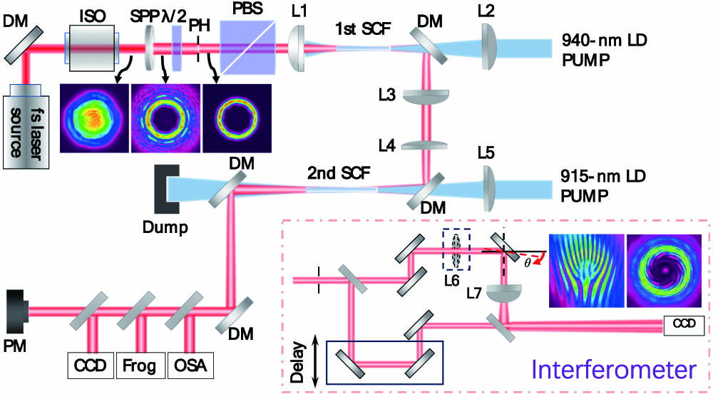
To alleviate the intensity-dependent SC generation and severe pulse broadening in the double-pass SCF amplification configuration [30], a two-stage single-pass amplification chain was employed. Figure 1 schematically shows the experimental setup where the seed source was a commercial -based femtosecond laser amplifier operating at 1026 nm (pulse duration, ; repetition rate, 1 MHz). The optical vortex () was produced by imprinting a helical phase onto the pre-existing fundamental beam through a fused-silica-based spiral phase plate with a total amount of steps of 512. Note that the total modal weighting of the modes with and radial index theoretically amounts to 32%, leading to a multi-outer-ring structure as shown by the inset. After passing through a pinhole, the unwanted outer rings were efficiently blocked resulting in a rather clean intensity profile serving as a seed; see the inset of Fig. 1. The seed beam was thereafter focused by a lens (L1, ) into the SCF with a measured spot diameter of 420 μm. A 30-mm-long (YAG) SCF (diameter of 970 μm, transmission loss of at 632.8 nm) doped with 1% (atom fraction) was employed in the first amplifier stage, and the corresponding pump source was a 150-W fiber-coupled (0.22 NA, 106-μm core diameter) laser diode (LD) at 940 nm. After reflection by a dichroic mirror, the amplified FOV was imaged into the second amplifier stage with a spot diameter of 630 μm by using a telescopic system consisting of L3 () and L4 (). A longer (40 mm) Yb:YAG SCF with the same dopant concentration and diameter was employed in this stage, pumping with a 210-W, fiber-coupled (0.16-NA, 135-μm core diameter) LD at 915 nm. To mitigate the thermal effects, both SCFs were directly water cooled in a specially designed aluminum module [32]. Finally, the spatial and temporal features were characterized by using a high-resolution (0.02 nm) optical spectrum analyzer, a second-harmonic generation (SHG)-FROG device, a CCD camera, and a power meter.
Figure 1.Schematic of the two-stage amplification system for the FOV with azimuthal mode index of , and the homemade Mach–Zehnder interferometer containing a delay line in one arm. Insets show the intensity profiles of the seed beam before and after passing through the SPP and PH, and the interferograms obtained with off-axis and co-axis self-reference measurements. DM, dichroic mirror; ISO, isolator; SPP, spiral phase plate; PH, pinhole; PBS, polarization beam splitter; L, lens; SCF, single-crystal fiber; LD, laser diode; PM, power meter; OSA, optical spectrum analyzer; FROG, frequency-resolved optical gating.
A Mach–Zehnder interferometer featuring a delay line in one of its arms was employed to obtain the interferograms and the corresponding phase information. As seen in Fig. 1, the reference beam was converted into a spherical wave using L7 (), enabling co-axis interference to produce spiral fringes. Due to the larger wavefront curvature of the reference compared to the vortex beam, the clockwise spiral fringe represents a negative OAM state though it can be easily switched after each reflection [33]. The phase of the FOV can be retrieved from the fork interferogram through two-dimensional Fourier and inverse Fourier transforms. Off-axis interference was realized by appropriately misaligning the two beams, where an additional lens (L6, ) was inserted into the other arm for beam shrinking.
B. Propagation Dynamics of Pump Light in the SCF
Because of its larger divergence compared to the seed laser, which undergoes free-space propagation in an SCF, the pump light is designed to be wave-guided. The propagation dynamics of the pump light inside the SCF was analyzed by ray-tracing and the resulting distributions are shown in Fig. 2. In the first amplifier stage, the pump beam was focused into the front part of the SCF with a spot diameter of μ, well matched with the seed beam size. As can be seen in Fig. 2(a), following the initial focusing, the beam diverged but was subsequently confined through total internal reflection, guiding it down to the fiber end and resulting in two optical Rayleigh ranges. The situation was quite similar in the second-stage SCF [see Fig. 2(b)], where a focal diameter of μ was employed to match the seed. The choice of a larger beam size, both for the pump and seed, serves to mitigate the risk of coating damage and enhance the critical power for SC generation. The corresponding on-axis intensity dependence along the SCFs is shown in Fig. 2(c). Segments of high-intensity distribution are observed, effectively lengthening the gain regions. Notably, for both cases, the transverse spatial intensity distribution maintains azimuthal uniformity at different positions along the SCF (as indicated by the insets). Consequently, the presence of discrete channels with azimuthally uniform pump intensity distribution offers advantageous conditions for amplification of optical vortices in contrast to traditional rod amplifiers where this part of the active element typically causes reabsorption at the laser wavelength to occur for the quasi-three-level laser system.
Figure 2.Simulated pump light spatial intensity distribution in the SCFs, where (a) represents the first-stage 30-mm-long SCF pumped by the 940-nm LD, (b) displays the second-stage 40-mm-long SCF pumped by the 915-nm LD, and (c) shows the corresponding normalized on-axis intensity distribution along the SCFs.
At first, we studied the power scaling capability of the first FOV amplifier stage in single pass. Figure 3(a) shows the performance of this stage independence on the seed level. The highest average output power of 12.5 W was obtained with the 2-W seed. Note that the FOV was directly amplified in the SCF without any pulse stretching and compression. The corresponding power stability was evaluated for 1 h. As can be seen in Fig. 3(b), the RMS stability amounted to 0.23%, indicating a stable power extraction. The intensity profiles and the corresponding self-inference patterns of the 2-W seed and the amplified FOV at 12.5 W are shown in Figs. 3(c)–3(h). Similar to the seed, both near- and far-field intensity profiles of the amplified FOV exhibited doughnut spatial shapes without thermally induced distortions. Moreover, the multiple outer-ring structure stemming from the nonzero radial index () modes in the seed beam, as displayed in Fig. 3(d), has been spatially filtered [see Fig. 3(g)] during amplification as a result of the larger divergence leading to lower gain or even reabsorption while passing through the peripheral part of the SCF. The clear clockwise spiral fringe in the self-interference pattern [see Fig. 3(h)] indicates that the wavefront of the FOV was well conserved benefiting from its free-space propagation in the SCF.
Figure 3.Average laser power and the corresponding gain of the (a) SCF amplifier stages and (b) power stability measurement. The bottom panel shows the recorded far-field (FF) and near-field (NF) intensity profiles and the corresponding self-interference patterns, where (c)–(e) correspond to the seed beam at 2 W, (f)–(h) show the FOV after the first amplifier stage at 12.5 W, (i)–(k) show the laser beam at 10.3 W which serves as a seed for the second amplifier stage, and (l)–(n) correspond to the second stage output at the highest power of 23 W. RMS, root mean square.
To increase the gain, a double-pass configuration with the first SCF was tested first by means of a quarter-wave plate and a reflective mirror (RM) [30]. A gain of 30 for a 0.1-W seed level was obtained at an absorbed pump power of 70 W, i.e., around 5 times higher than in single-pass amplification under the same pump level. However, severe spectral narrowing and temporal broadening of the pulse were observed in this case. Moreover, parasitic laser oscillation between the RM and a damage spot on the entrance face of the SCF occurred when further increasing the pump power.
Consequently, a two-stage amplifier system was employed for further power scaling in order to maintain the temporal properties. To mitigate the thermal effects and avoid the risk of SCF damage, a longer (40 mm) SCF and a 915-nm LD pump source (lower absorption cross section compared to that at 940 nm [34]) were employed in the second stage. By seeding a 10.3-W FOV, as can be seen in Fig. 3(a), a maximum average power of 23 W was achieved at the output of the second stage corresponding to a single pulse energy of 23 μJ at 1 MHz. Figure 3(b) shows the measured power stability of the second amplifier stage at an output level of (a safe power level in long-term operation) estimated to be 0.55% RMS. Such stability is evidence for the overall robustness of the entire SCF amplifier system. The spatial features of the 10.3-W seed and the amplified 23-W FOV are shown in Figs. 3(i)–3(n). No visible beam distortion is encountered and the slightly nonuniform azimuthal intensity distribution is due to the nonuniform ion distribution across the cross section of the SCF. A weak, small central spot [see Fig. 3(l)] appeared at high output power levels (), which may be caused by the diffraction of amplified residual modes. Nevertheless, the near-field beam profile [see Fig. 3(m)] exhibits a clean doughnut intensity distribution with a singularity noise contrast of , and the interferogram in Fig. 3(n) shows clear spiral fringes. The well conserved spatial properties also confirm the straightforward power scaling capability of such an SCF amplifier system for high-order FOV.
B. Spectral Evolution and Temporal Properties
Figure 4(a) shows the spectral evolution in the two-stage SCF amplifier. In the first amplifier stage at a seed level of 2 W, no nonlinear spectral broadening was observed, and the optical spectra roughly maintained their original bandwidth. The slight spectral narrowing of the main peak with increasing power was due to the gain narrowing effect. This spectral narrowing effect was significant for low-power seeding or when employing the double-pass configuration. The temporal features of the amplified FOV were characterized by using SHG-FROG. Figure 4(b) shows the retrieved temporal and spectral profiles with the corresponding phase information of the FOV at 12.5-W output power from the first stage. The derived pulse duration is 130 fs, slightly longer than the seed pulse width due to the group delay dispersion (GDD, [35]) of the 30-mm-long Yb:YAG SCF.
Figure 4.(a) Spectral evolution of the FOV in the two-stage SCF amplifier system, and the SHG-FROG characterization ( grids) of the FOV (b) after the first amplifier stage at an average output power 12.5 W and (c) after the second stage at 23 W.
In the second amplifier stage, the FOV experienced noticeable spectral broadening due to self-phase modulation (SPM) during propagation [36] in the 40-mm-long SCF. As can be seen in Fig. 4(a), such nonlinear spectral broadening was more significant when increasing the pump power. At the highest average output power of 23 W the optical spectrum spanned from 990 to 1040 nm at the 10% level. The corresponding temporal characteristics are shown in Fig. 4(c). The pulse duration increased to 163 fs which can be accounted for by the total GDD () in the two SCF stages. Nevertheless, the spectral broadening due to SPM indicates the possibility for subsequent pulse compression by using dispersive mirrors with high negative GDD [35]. Note that the highest peak power achieved from the second stage exceeded 0.14 GW, which will be a challenge for a conventional silica fiber Yb-amplifier without stretching and compression [20,26], which emphasizes again the feasibility of SCFs for amplification of high-order FOVs.
C. Spatial Phase and Modal Purity
To visualize the phase structure, fork interferograms were recorded through off-axis interference. Figures 5(a) and 5(b) show the intensity and the corresponding interferogram of the 12.5-W FOV after the first amplification stage. The nine clear bright fringes with downward direction indicate a high purity mode with an azimuthal index of . Subsequently, the spatial phase structure was retrieved from the interferogram by using two-dimensional Fourier and inverse Fourier transforms. As shown in Fig. 5(c), eight sections with a phase change of in each of them again confirm the OAM state of . A similar situation was also observed at the highest output power of 23 W after the second amplification stage [see Figs. 5(d)–5(f)], indicating that both the spatial intensity and phase structures were well-conserved in the entire SCF amplifier system.
Figure 5.(a) Intensity profile, (b) off-axis interference fringe pattern, and (c) the retrieved screw-like phase structure for the 12.5-W FOV from the first amplification stage. (d)–(f) represent the corresponding images after the second amplification stage at 23 W. (g) shows the calculated relative modal weighting for both cases.
To further evaluate the modal purity of the amplified FOVs, the relative modal weighting was calculated by decomposing the laser beams through the following function [37]: where represents the electric field of the experimental FOV obtained with the retrieved phase and amplitude, and is the complete basis set of modes. As can be seen in Fig. 5(g), the modal portion of the OAM state with was calculated to be 97.3% and 96% in the first-stage and second-stage amplified FOV beams, respectively. This high weighting proves that the reduction of the modal purity during the amplification is negligible and confirms the potential of the SCF amplifier system for direct amplification of FOVs.
4. CONCLUSION
In conclusion, we have demonstrated direct amplification of a high-order FOV in a two-stage single-pass SCF amplifier system, delivering 23-μJ, 163-fs scalar FOV at 1 MHz with an OAM state of . No noticeable beam distortion [23] or mode perturbation [20,25] is seen and it can be concluded that the twisted spatial phase and high modal purity were well maintained during the amplification. In addition, no pulse distortion due to nonlinear effects was observed in the time domain, and the slight broadening of pulse duration was mainly due to linear chirp from the material dispersion. The achieved power scaling is attributed to the pump guiding, which is an inherent feature of the SCF, providing a long gain region with azimuthally uniform intensity distribution to overcome the intrinsic mode mismatch between the doughnut-shaped vortex and quasi-top-hat pump light. On the other hand, owing to the free-space propagation and the weak thermal effects in the SCF offering a large surface-to-volume ratio, the spatial and temporal features of the FOV are well-conserved during amplification.
This work demonstrates the potential of multi-stage SCF amplifiers for direct amplification of FOVs. The achieved high-average-power FOVs will pave the way for real applications in diverse fields such as nonlinear optics and fine structuring of chiral materials. The absence of roll-off effects in the power dependence indicates that further scaling should be possible by increasing the pump level. This will require optimization of the SCF design and in particular the diameter and the length of the SCFs for highest efficiency. Moreover, we believe the approach presented here is in principle also feasible for direct amplification of other forms of CW or pulsed structured light, such as vector beams with arbitrary orders [38], kaleidoscope modes [39], polygonal perfect vortex beams [40], or even optical vortex arrays [41].
Acknowledgment
Acknowledgment. We thank Dr. J. Guo from Jiangsu Collaborative Innovation Center of Advanced Laser Technology and Emerging Industry, Jiangsu Normal University, China, for discussion and calculation of the modal purity.
 AI Video Guide
  AI Picture Guide
 AI One Sentence