• Chinese Optics Letters
  • Vol. 16, Issue 5, 050004 (2018)
Yaoran Liu, Zilong Wu, Eric H. Hill, and Yuebing Zheng*
Author Affiliations
  • Department of Mechanical Engineering and Texas Materials Institute, The University of Texas at Austin, Austin, Texas 78712, USA
  • show less
    DOI: 10.3788/COL201816.050004 Cite this Article Set citation alerts
    Yaoran Liu, Zilong Wu, Eric H. Hill, Yuebing Zheng. Mid-infrared superabsorbers based on quasi-periodic moiré metasurfaces[J]. Chinese Optics Letters, 2018, 16(5): 050004 Copy Citation Text show less
    (a) Fabrication procedure of MIM moiré superabsorbers with variable parameters (i.e., spacer thickness d, rotation angle θ, and filling factor). (b)-(d) Moiré metasurfaces with variable rotation angles of 10°, 15°, and 20°, respectively. (e) 20° moiré metasurface with a higher filling factor than that in (d). (f), (g) Scanning electron micrographs of Au moiré metasurfaces. The scale bar is 2 μm.
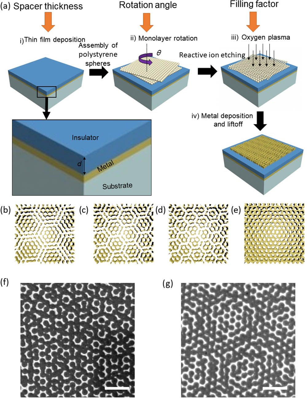
    Fig. 1. (a) Fabrication procedure of MIM moiré superabsorbers with variable parameters (i.e., spacer thickness d, rotation angle θ, and filling factor). (b)-(d) Moiré metasurfaces with variable rotation angles of 10°, 15°, and 20°, respectively. (e) 20° moiré metasurface with a higher filling factor than that in (d). (f), (g) Scanning electron micrographs of Au moiré metasurfaces. The scale bar is 2 μm.
    (a) Unit vectors in the hexagonal hole array. (b) A rectangular area in the hexagonal hole array using V(5,8) and V′(1,6) as the length and width separately. (c) The same area as (b) but with a relative ∼15° rotation angle. (d) A unit cell in the moiré pattern with a relative ∼15° rotation angle. (e) A unit cell for 10°, 15°, and 20° moiré metasurfaces.
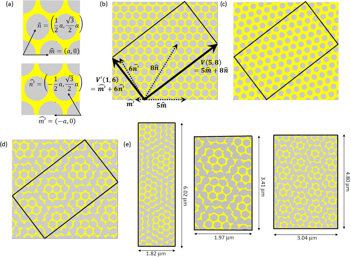
    Fig. 2. (a) Unit vectors in the hexagonal hole array. (b) A rectangular area in the hexagonal hole array using V(5,8) and V(1,6) as the length and width separately. (c) The same area as (b) but with a relative 15° rotation angle. (d) A unit cell in the moiré pattern with a relative 15° rotation angle. (e) A unit cell for 10°, 15°, and 20° moiré metasurfaces.
    (a) Cross-sectional view of r12′, r21′, t12′, and t21′ in decoupled mode theory. (b) The simulation model to calculate the parameters r12′, r21′, t12′, and t21′. (c) The simulated reflection/transmission phase and amplitude coefficients for a 15° rotation angle moiré metasurface.
    Fig. 3. (a) Cross-sectional view of r12, r21, t12, and t21 in decoupled mode theory. (b) The simulation model to calculate the parameters r12, r21, t12, and t21. (c) The simulated reflection/transmission phase and amplitude coefficients for a 15° rotation angle moiré metasurface.
    (a) Simulated (black dashed line) absorption for a 15° rotation angle pristine (no spacer) moiré metasurface; simulated (dashed red and blue line) and calculated (solid black line) results comparison for a 15° rotation angle moiré MIM structure with 800 nm spacer thickness. The PML boundary is applied in the simulation. (b) Simulated (dashed line) and calculated (solid line) results comparison for different rotation angles at 800 nm spacer thickness. The periodic boundary is applied in the simulation.
    Fig. 4. (a) Simulated (black dashed line) absorption for a 15° rotation angle pristine (no spacer) moiré metasurface; simulated (dashed red and blue line) and calculated (solid black line) results comparison for a 15° rotation angle moiré MIM structure with 800 nm spacer thickness. The PML boundary is applied in the simulation. (b) Simulated (dashed line) and calculated (solid line) results comparison for different rotation angles at 800 nm spacer thickness. The periodic boundary is applied in the simulation.
    (a) Calculated narrowband absorber with an optimized spacer thickness (1300 nm) at different rotation angles. (b) A calculated broadband absorber with an optimized spacer thickness (900 nm spacer for 10°, 800 nm spacer for 15°, and 700 nm spacer for 20°).
    Fig. 5. (a) Calculated narrowband absorber with an optimized spacer thickness (1300 nm) at different rotation angles. (b) A calculated broadband absorber with an optimized spacer thickness (900 nm spacer for 10°, 800 nm spacer for 15°, and 700 nm spacer for 20°).
    (a) Simulated polarization-dependent broadband absorption for a 20° moiré MIM structure with an optimized spacer thickness. (b) Simulated polarization-dependent narrowband absorption for a 20° moiré MIM structure with an optimized spacer thickness.
    Fig. 6. (a) Simulated polarization-dependent broadband absorption for a 20° moiré MIM structure with an optimized spacer thickness. (b) Simulated polarization-dependent narrowband absorption for a 20° moiré MIM structure with an optimized spacer thickness.
    Simulated visible-NIR absorption spectra of a 10° moiré MIM structure with different spacer thicknesses.
    Fig. 7. Simulated visible-NIR absorption spectra of a 10° moiré MIM structure with different spacer thicknesses.
    Rotation AngleTolerancemmnn
    15°δ=0.11115
    15°δ=0.015186
    15°δ=0.00117112767
    Table 1. m, m′, n, and n′ Values for Different Tolerance Factors as θ Equals 15°
    Rotation AngleTolerancemmnn
    10°δ=0.0132419
    15°δ=0.015186
    20°δ=0.0162119
    Table 2. m, m′, n, and n′ Values Used in Simulation for Different Rotation Angles
    Yaoran Liu, Zilong Wu, Eric H. Hill, Yuebing Zheng. Mid-infrared superabsorbers based on quasi-periodic moiré metasurfaces[J]. Chinese Optics Letters, 2018, 16(5): 050004
    Download Citation