
J. Hornung, Y. Zobus, P. Boller, C. Brabetz, U. Eisenbarth, T. Kühl, Zs. Major, J. B. Ohland, M. Zepf, B. Zielbauer, V. Bagnoud. Enhancement of the laser-driven proton source at PHELIX[J]. High Power Laser Science and Engineering, 2020, 8(2): 02000e24
- High Power Laser Science and Engineering
- Vol. 8, Issue 2, 02000e24 (2020)
Abstract
1 Introduction
Within the past two decades, an extensive amount of work has been conducted on the topic of laser-driven proton acceleration, motivated by the unprecedented properties offered by such a particle source. Indeed the emittance and time duration of a laser-driven proton beam are many orders of magnitude lower than those for conventional accelerators[
Even though there exists a large amount of research on TNSA, there is still a significant discrepancy in the experimental data reported by the laboratories working in this field[
These parameters can be systematically controlled at the PHELIX laser (
Sign up for High Power Laser Science and Engineering TOC. Get the latest issue of High Power Laser Science and Engineering delivered right to you!Sign up now
On the way to generate reproducible proton beams, which can be used for further applications, we present a study at PHELIX comparing the influence on the ion acceleration when using a last focusing optic made of high-quality
2 Setup
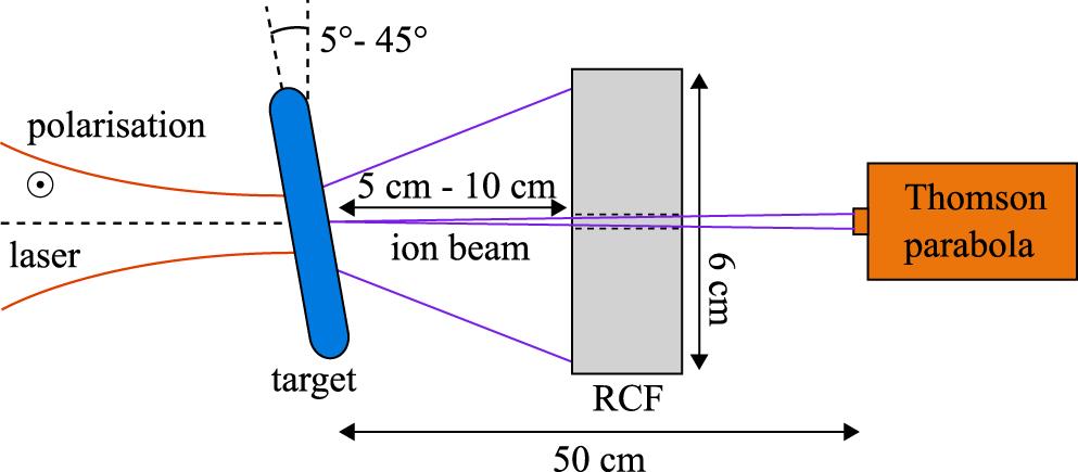
The experiments were conducted during two different campaigns, using a similar setup as shown in Figure
The accelerated ions are caught by a stack of radiochromic films (RCFs) layered in between Mylar foils. For the first campaign using an interaction angle close to normal incidence, the stack was placed in the laser direction at a distance of 10 cm. For the second campaign, the interaction angle was increased to
The targets, which were manufactured at the Technische Universität Darmstadt, consist of flat foils attached to small
To ensure similar conditions during all shots, the beam properties are monitored at different positions in the laser chain of PHELIX. The on-shot diagnostics, measuring near- and far-field, are placed behind the main amplifier and the compressor. Additionally, the wavefront is measured after the main amplifier, using a home-made Shack–Hartmann sensor and control software[
3 Overall laser performance
The laser parameters have a decisive influence on particle acceleration. Since the on-target laser intensity cannot be measured directly, it is always inferred from the measurement of the pulse energy, the pulse duration and the focal-spot fluence distribution. The latter is not measured on-shot but during alignment with the un-amplified beam.
The on-shot energy is measured at the output of the main amplifier using a pyroelectric detector located behind a leaky mirror. This detector is cross-calibrated with a full-beam-size calorimeter capable of measuring the energy of the full beam in a range from 20 J to 5 kJ, located before the leaky mirror. This calorimeter can be self-calibrated using resistive ohmic heating to deliver absolute energy measurements. Additional passive losses introduced by the compressor and transportation to the target chamber can also be measured by a second pyrometric detector located inside the target chamber. These measurements add up to a total uncertainty of the energy of
The focal spot is measured with a Plan Apochromat microscope objective, which is aligned in the laser direction, with the image relaying the focus to the centre of a 16-bit camera chip (Hamamatsu ORCA-flash4.0 LT) located outside of the target chamber. The imaging is in total carried out by two telescopes with a total magnification of 8. After the initial alignment, the camera centre and the focal position define the target chamber centre (TCC), onto which the targets are aligned later on. The exact magnification factor is determined by moving a sharp edge in the imaging plane by a known magnitude, typically
This measurement of the focus is additionally multiplied by an on-shot factor, which is obtained by dividing the maximum value in the far-field at the compressor diagnostic on-shot, by the value obtained prior to the shot in low energy mode, after normalizing them to the integral of the signal. This shows an increased area on-shot in which the energy is distributed, leading to an estimated on-shot intensity of only (
A larger impact on the intensity is given by the pulse duration, which was measured inside the target chamber, using a device based on FROG[
In addition, the knowledge of the temporal profile of the pulse on a high dynamic range is essential, and its characteristics such as the amplified spontaneous emission (ASE) background, the specific shape of the rising slope on a picosecond time scale and the possible presence of pre-pulses may alter the target condition at the time of the interaction and prevent the use of ultra-thin targets. For this reason, the temporal contrast has to be measured with a very high dynamic range, covering 12 orders of magnitude, and a wide temporal window of 2.5 ns prior to the peak intensity[
All of these parameters have an influence on the maximum proton energy that is attainable, but only some of these can be improved with a reasonably small effort.
4 Influence of the focus quality on the proton beam
A well-known approach for enhancing the maximum proton energy and particle numbers is to increase the on-target laser intensity[
The situation is more complicated in and after the compressor, where the wavefront errors of the gratings (
To confirm the impact of the diamond-turned parabola compared to the performance with a high-end focusing element, we exchanged the copper parabola with a dielectrically coated high-quality parabolic mirror having the same geometrical properties. This parabola exhibits a better reflected wavefront error of
Quantitatively, one can see a strong reduction of the coma-like aberration, which distributes more energy in the outer region of the focal spot. This improvement can also be quantified by looking at the encircled energy for both parabolas (bottom). The energy within a radius of
To evaluate the effect of this improvement on the accelerated ion characteristics, a dedicated experiment was conducted, checking the scaling of maximum proton energy and laser intensity. This is done by focusing the laser onto a 300-nm-thin polystyrene target with an incidence angle of
By doing so, we quickly realized that the 300-nm-thin targets showed some signs of boring for the higher laser energies when the copper parabola was used. An indicator of this is an increase in the blurred electron background seen in the RCFs[
In addition, one can see that the shots carried out with the glass parabola delivered the highest proton maximum energies. For an estimated intensity of
Although this represents a new record for protons accelerated at PHELIX, the values obtained show only a slight improvement compared to previous data published by our group[
The first explanation for the deviation from the
The second reason for that could be related to the energy distribution, since the central spot of the focus gains energy, and therefore intensity when using the glass parabola, but its surrounding loses energy. This would lead to an increased contribution to the acceleration at the centre, and a reduction in the impact from the outer regions, only leading to a minor total increase.
Since the scaling of the maximum proton energy with the laser intensity does not seem conclusive to draw a rule of thumb, a better picture can be obtained from a scaling law based on the laser peak power, as shown in Figure
The conclusion to this first study is that the use of a better optical focusing element brings a measurable although slight improvement to laser-driven ion acceleration, with a new record of
5 Enhancement of the proton source for day-to-day operation
As mentioned, it is of interest to reduce the amount of debris deposited on the focusing element and therefore the operation cost. Many of the usual methods relying on the use of a debris shield are hard to implement at PHELIX because of the combined difficulties arising from the short pulse duration, the large beam size and the incidence angle of
There are two strategies that can easily be implemented at PHELIX to increase laser absorption. One possibility is of increasing the preplasma formation[
Both approaches have been tested and compared to the regular setup with s-polarization, a high temporal contrast of
The first configuration is carried out with a nanosecond temporal contrast of
The dependence of the maximum proton energy on the peak power for the three different setups can be seen in Figure
We reconstructed the proton energy spectra based on the RCF stack available and plotted the results for the various configurations, which were obtained with similar laser powers, in Figure
Figure
6 Summary
We have performed two experimental campaigns, focusing on the enhancement of laser-ion acceleration with the high-power laser PHELIX. The goal of these was to optimize the maximum achievable proton energy and particle numbers, while working under experimental conditions that minimize operation cost. This was done by improving the quality of the focal spot, which increased the expected intensity by a factor of 2.8 up to
References
[1] T. E. Cowan, J. Fuchs, H. Ruhl, A. Kemp, P. Audebert, M. Roth, R. Stephens, I. Barton, A. Blazevic, E. Brambrink, J. Cobble, J. Fernández, J.-C. Gauthier, M. Geissel, M. Hegelich, J. Kaae, S. Karsch, G. P. Le Sage, S. Letzring, M. Manclossi, S. Meyroneinc, A. Newkirk, H. Pépin, N. Renard-LeGalloudec. Phys. Rev. Lett., 92(2004).
[2] S. S. Bulanov, A. Brantov, V. Y. Bychenkov, V. Chvykov, G. Kalinchenko, T. Matsuoka, P. Rousseau, S. Reed, V. Yanovsky, K. Krushelnick, D. W. Litzenberg, A. Maksimchuk. Med. Phys., 35, 1770(2008).
[3] M. Roth, T. E. Cowan, M. H. Key, S. P. Hatchett, C. Brown, W. Fountain, J. Johnson, D. M. Pennington, R. A. Snavely, S. C. Wilks, K. Yasuike, H. Ruhl, F. Pegoraro, S. V. Bulanov, E. M. Campbell, M. D. Perry, H. Powell. Phys. Rev. Lett., 86, 436(2001).
[4] M. Roth, D. Jung, K. Falk, N. Guler, O. Deppert, M. Devlin, A. Favalli, J. Fernandez, D. Gautier, M. Geissel, R. Haight, C. E. Hamilton, B. M. Hegelich, R. P. Johnson, F. Merrill, G. Schaumann, K. Schoenberg, M. Schollmeier, T. Shimada, T. Taddeucci, J. L. Tybo, F. Wagner, S. A. Wender, C. H. Wilde, G. A. Wurden. Phys. Rev. Lett., 110(2013).
[5] A. P. L. Robinson, M. Zepf, S. Kar, R. G. Evans, C. Bellei. New J. Phys., 10(2008).
[6] C. M. Brenner, A. P. L. Robinson, K. Markey, R. H. H. Scott, R. J. Gray, M. Rosinski, O. Deppert, J. Badziak, D. Batani, J. R. Davies, S. M. Hassan, K. L. Lancaster, K. Li, I. O. Musgrave, P. A. Norreys, J. Pasley, M. Roth, H.-P. Schlenvoigt, C. Spindloe, M. Tatarakis, T. Winstone, J. Wolowski, D. Wyatt, P. McKenna, D. Neely. Appl. Phys. Lett., 104(2014).
[7] M. Borghesi, J. Fuchs, S. V. Bulanov, A. J. MacKinnon, P. K. Patel, M. Roth. Fusion Sci. Technol., 49, 412(2006).
[8] H. Daido, M. Nishiuchi, A. S. Pirozhkov. Rep. Progr. Phys., 75(2012).
[9] A. Macchi, M. Borghesi, M. Passoni. Rev. Modern Phys., 85, 751(2013).
[10] J. Fuchs, P. Antici, E. d’Humières, E. Lefebvre, M. Borghesi, E. Brambrink, C. A. Cecchetti, M. Kaluza, V. Malka, M. Manclossi, S. Meyroneinc, P. Mora, J. Schreiber, T. Toncian, H. Pépin, P. Audebert. Nat. Phys., 2, 48(2006).
[11] R. J. Gray, D. C. Carroll, X. H. Yuan, C. M. Brenner, M. Burza, M. Coury, K. L. Lancaster, X. X. Lin, Y. T. Li, D. Neely, M. N. Quinn, O. Tresca, C.-G. Wahlström, P. McKenna. New J. Phys., 16(2014).
[12] V. Bagnoud, B. Aurand, A. Blazevic, S. Borneis, C. Bruske, B. Ecker, U. Eisenbarth, J. Fils, A. Frank, E. Gaul, S. Goette, C. Haefner, T. Hahn, K. Harres, H.-M. Heuck, D. Hochhaus, D. H. H. Hoffmann, D. Javorková, H.-J. Kluge, T. Kühl, S. Kunzer, M. Kreutz, T. Merz-Mantwill, P. Neumayer, E. Onkels, D. Reemts, O. Rosmej, M. Roth, T. Stoehlker, A. Tauschwitz, B. Zielbauer, D. Zimmer, K. Witte. Appl. Phys. B, 100, 137(2010).
[13] V. Bagnoud, F. Wagner. High Power Laser Sci. Eng., 4(2016).
[14] N. Schroeter. Development and calibration of a high-dispersive Thomson parabola for laser-driven ion beams. Masterarbeit, Technische Universität Darmstadt (2017)..
[15] P. Kaw, J. Dawson. Phys. Fluids, 13, 472(1970).
[16] L. Yin, B. J. Albright, B. M. Hegelich, J. C. Fernández. Laser Part. Beams, 24, 291(2006).
[17] J. B. Ohland, U. Eisenbarth, C. Brabetz, V. Bagnoud, M. Roth8th Conference of the International Committee on Ultrahigh Intensity Lasers, Lindau. and in (2018)..
[18] D. J. Kane, R. Trebino. Opt. Lett., 18, 823(1993).
[19] V. A. Schanz, C. Brabetz, D. J. Posor, D. Reemts, M. Roth, V. Bagnoud. Appl. Phys. B, 125, 61(2019).
[20] K. Zeil, S. D. Kraft, S. Bock, M. Bussmann, T. E. Cowan, T. Kluge, J. Metzkes, T. Richter, R. Sauerbrey, U. Schramm. New J. Phys., 12(2010).
[21] R. Nuter, L. Gremillet, P. Combis, M. Drouin, E. Lefebvre, A. Flacco, V. Malka. J. Appl. Phys., 104(2008).
[22] A. Higginson, R. J. Gray, R. J. Dance, S. D. R. Williamson, N. M. H. Butler, R. Wilson, R. Capdessus, C. Armstrong, J. S. Green, S. J. Hawkes, P. Martin, W. Q. Wei, S. R. Mirfayzi, X. H. Yuan, M. Borghesi, R. J. Clarke, D. Neely, P. McKenna. Nat. Commun., 9, 724(2018).
[23] I. J. Kim, K. H. Pae, I. W. Choi, C.-L. Lee, H. T. Kim, H. Singhal, J. H. Sung, S. K. Lee, H. W. Lee, P. V. Nickles, T. M. Jeong, C. M. Kim, C. H. Nam. Phys. Plasmas, 23(2016).
[24] F. Wagner, O. Deppert, C. Brabetz, P. Fiala, A. Kleinschmidt, P. Poth, V. A. Schanz, A. Tebartz, B. Zielbauer, M. Roth, T. Stöhlker, V. Bagnoud. Phys. Rev. Lett., 116(2016).
[25] P. Mora. Phys. Rev. Lett., 90(2003).
[26] J. Schreiber, F. Bell, F. Grüner, U. Schramm, M. Geissler, M. Schürer, S. Ter-Avetisyan, B. M. Hegelich, J. Cobble, E. Brambrik, J. Fuchs, P. Audebert, D. Habs. Phys. Rev. Lett., 97(2006).
[27] T. Esirkepov, M. Yamagiwa, T. Tajima. Phys. Rev. Lett., 96(2006).
[28] Y. Ping, R. Shepherd, B. F. Lasinski, M. Tabak, H. Chen, H. K. Chung, K. B. Fournier, S. B. Hansen, A. Kemp, D. A. Liedahl, K. Widmann, S. C. Wilks, W. Rozmusand, M. Sherlock. Phys. Rev. Lett., 100(2008).
[29] F. Wagner, C. P. João, J. Fils, T. Gottschall, J. Hein, J. Körner, J. Limpert, M. Roth, T. Stöhlker, V. Bagnoud. Appl. Phys. B, 116, 429(2014).
[30] L. M. Chen, J. Zhang, Q. L. Dong, H. Teng, T. J. Liang, L. Z. Zhao, Z. Y. Wei. Phys. Plasmas, 8, 2925(2001).
[31] D. Bauer, P. Mulser. Phys. Plasmas, 14(2007).

Set citation alerts for the article
Please enter your email address
© Copyright 2018-2021 | Chinese Laser Press. All Rights Reserved 沪ICP备15018463号-20