Ekaterina I. Gacheva1, Anatoly K. Poteomkin1, Sergey Yu. Mironov1, Viktor V. Zelenogorskii1..., Efim A. Khazanov1,2, Konstantin B. Yushkov2,*, Alexander I. Chizhikov2 and Vladimir Ya. Molchanov2|Show fewer author(s)
Abstract
We report on the design and performance of a fiber laser system with adaptive acousto-optic macropulse control for a novel photocathode laser driver with 3D ellipsoidal pulse shaping. The laser system incorporates a three-stage fiber amplifier with an integrated acousto-optical modulator. A digital electronic control system with feedback combines the functions of the arbitrary micropulse selection and modulation resulting in macropulse envelope profiling. As a benefit, a narrow temporal transparency window of the modulator, comparable to a laser pulse repetition period, effectively improves temporal contrast. In experiments, we demonstrated rectangular laser pulse train profiling at the output of a three-cascade Yb-doped fiber amplifier.1. INTRODUCTION
During the last decade many laboratories around the world (CERN, KEK, JINR, PITZ, SLAC) focused on development and implementation of laser-driven photocathodes for electron injection in linear accelerators (photoinjectors) [1]. The only way to obtain a time structure of an electron beam in the form of separated electron bunches with small emittance and hence with high brightness is to illuminate a photocathode by short (several tens of picoseconds) laser pulses. In advanced facilities, 3D profiling of laser pulses is used. In addition, a photoinjector is the best solution for synchronization of electron bunches with a radio-frequency electromagnetic field in an accelerating cavity due to a stable and tunable laser pulse repetition rate. Such electron sources are of a critical importance in many applications, for example, in free-electron lasers and electron-positron colliders.
Usually, a laser driver for a photoinjector should irradiate identical pulses (hereinafter we call them micropulses) at a repetition rate of several megahertzs, grouped into pulse trains (macropulses) with several tens of microseconds duration and 1–100 Hz repetition rate. Depending on the choice of the photocathode material, an output wavelength of the laser driver and a demanded micropulse energy are defined. The most widely used today are cesium-telluride high quantum efficiency photocathodes. They require 1–10 μJ energy at a wavelength of around 270 nm to generate electron bunches with nC-level charge.
An adaptive correction of a macropulse envelope is a particular problem of photoinjector laser design. Much research has been made on macropulse amplification with a rectangular temporal profile, but none helps us to cope with distortions in other elements of the scheme [2–5]. In recent years, acousto-optic methods of ultrashort laser pulse controlling have made considerable progress. Acousto-optic devices are used for adaptive pulse shaping [6–8], spectral gain correction in regenerative amplifiers [9], sub-THz profiling of chirped pulses [10], phase and amplitude stabilization of femtosecond master oscillators (MOs) [11,12], etc. Intracavity acousto-optic devices can be used for tuning optical parametric oscillators and fiber lasers [13,14]. A Doppler shift of diffracted laser emission can provide additional flexibility of pulse-shape generation [15]. A number of successful applications of fiber-coupled bulk acoustic wave acousto-optic devices also has been reported [16–21]. Acousto-optic modulators (AOMs) are commonly used as pulse pickers in ultrafast laser systems, but their conventional function is limited to on/off switching with a fixed duty cycle [12,21–23]. AOMs also have been used for amplitude shaping of macropulses providing slow (compared with pulse repetition rate) correction for the envelope distorted by gain saturation and nonlinear losses in a laser system [24–27].
Sign up for Photonics Research TOC. Get the latest issue of Photonics Research delivered right to you!Sign up now
In this research, we designed a fiber laser integrated with an adaptive acousto-optic system providing programmable random access micropulse control. This laser system was designed in IAP RAS as a front-end part intended for a novel photoinjector driver with 3D pulse shaping by means of volume chirped Bragg gratings [28]. A single fiber-coupled AOM is used as a pulse selector and a macropulse envelope shaper simultaneously.
2. LASER DRIVER SCHEME
Figure 1 shows a simplified block diagram of the laser driver. Elements that do not affect the macropulse temporal profile are not shown. The scheme starts from a low-power MO. It works in a self-mode-locking regime and irradiates a continuous chain of identical short () micropulses at repetition rate. As MO repetition rate is higher than required for the application, fiber-coupled AOM transmits each th pulse through a 20 ns temporal transparency window. Each macropulse is a set of a predefined number of micropulses. For the photoinjector application, the micropulses should be equally spaced but the driver electronics are not limited to this regime and can provide micropulse selection with arbitrary integer-valued intervals. The AOM is closed under the normal conditions, which allows time-domain suppression of luminescence originating from the first fiber amplifier. Besides the pulse selection function, the AOM is used to control the amplitude of transmitted micropulses, as described in Section 4. A digital pulse control system adjusts the AOM transmission individually for each micropulse. Thus it can compensate for temporal distortions caused by any element of the scheme, no matter before or after the AOM.
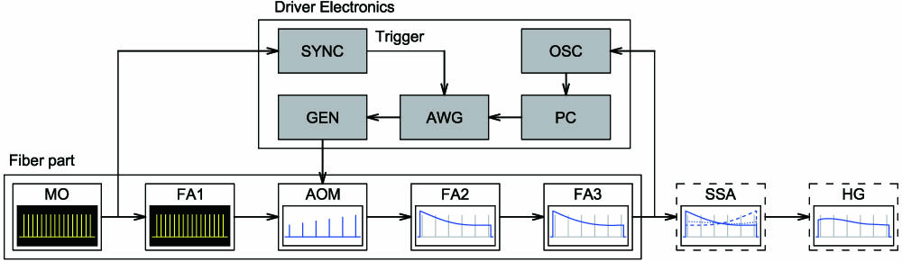
Figure 1.Simplified block diagram of the photocathode laser driver. FA1, FA2, FA3, fiber amplifiers; HG, harmonic generator; SYNC, electronic synchronization unit; OSC, digital oscilloscope; PC, computer; AWG, arbitrary waveform generator; GEN, RF generator. Yellow on black are radiation oscillograms; blue on white are temporal transmission profiles of the scheme elements. Dashed blocks (non-fiber elements) are under development in the described laser system.
There are three cascades of fiber amplification (FA) in the system. The final stage is planned to be a powerful solid-state amplifier (SSA). Thus, we managed to avoid preliminary amplification in thick fiber and to work with single-mode Yb-doped fibers pumped continuously through the core. Such amplifiers can be entirely assembled of standard telecommunication components; they are cheap and reliable. Some modules (not shown at the scheme) are also installed between the FA cascades for micropulse time profiling. These modules introduce significant power loss, which makes the problem of luminescence amplification in Yb-doped fiber more urgent and increases the demand for the AOM as a temporal gate. Because the fiber amplifiers are continuously pumped, saturation of amplification leads to a monotonously decreasing distorted macropulse envelope. The pulse energy in the fiber amplifier is limited by cubic nonlinearity self-modulation.
The final stage of the system is a free space SSA. By using a pulsed pump in a “prepumping” regime, high peak power in the output macropulse can be achieved [29]. In this mode of operation, the pump turns on earlier than the input macropulse appears, which allows preparing the inversion in the active medium before the amplification process. “Prepumping” time and macropulse duration are usually of the same magnitude order as laser transition lifetime. Depending on “prepumping” time , a negative-going (), quasi-rectangular () or increasing () envelope can be obtained from an initially rectangular macropulse. The last case also helps to compensate partly distortions originated from the fiber amplifiers. Relation leads to a higher amplification coefficient even if additional correction in the AOM is needed. The problem of equilibrium value of time has been discussed in detail in Ref. [29]. However, gain saturation in FAs cannot be simply compensated by underpumping of the SSA. Macropulse distortion function anyway will contain high-order polynomials, and the AOM is required for precise correction.
After the SSA, laser radiation is converted into the second and the fourth harmonics in nonlinear crystals. BBO crystal is chosen for the fourth harmonic generator due to its high nonlinearity, and broad synchronism can cause considerable non-monotonous distortion of the macropulse envelope. This effect is caused by generation of temporal (so-called “grey”) absorption centers in nonlinear two-photon absorption processes in crystal volume. “Grey” centers absorb linearly in the broad spectral range. Their accumulation at macropulse duration together with confusing synchronism adjustment (maximal output energy is achieved not in synchronism for the first micropulse of the train) leads to peculiar macropulse distortions [27]. The final goal of rectangular macropulse profiling by the AOM is to compensate for the overall temporal transmission profile of all the described optical elements using forth harmonic output as a feedback signal.
3. ACOUSTO-OPTIC PULSE CONTROL SYSTEM
The pulse control system consists of an AOM with a digital feedback loop, as shown in Fig. 1. An electronic control system digitizes the output intensity envelope of the laser and uses it for correction of the AOM transmission. The pulse picking ratio and the length of the macropulse are defined by the operation regime of the laser, while the intensity of each micropulse can be either manually defined or adaptively adjusted using the feedback system to provide the desired output macropulse envelope.
The fiber-coupled AOM is based on a paratellurite single crystal. The incident optical beam, which propagates along the [110] axis, is diffracted by the longitudinal bulk ultrasonic wave propagating along the [001] axis with the phase velocity of 4200 m/s. The difference between the acousto-optic figure of merit values for two orthogonal polarizations in this configuration is approximately 10%. The carrier frequency of the AOM has been chosen equal to 200 MHz; the modulation frequency FWHM bandwidth was equal to 40 MHz. The ratio of light to ultrasound divergences corresponding to the central wavelength is less than 0.5. In this case, the rise and the fall times of modulation are equal at high diffraction efficiency level, and the diffracted beam profile distortions are minimal [30,31]. The rise time of the AOM equals to 10 ns (for 10%–90% intensity levels). This AOM configuration ensured high contrast of the 47.6 MHz pulse train modulation of the laser emission with a relatively narrow spectrum . Because the AOM operates with isotropic diffraction of light by ultrasound, the issues of group mismatch between incident and diffracted light described in Ref. [32] do not occur.
The driver electronic circuit feeding the AOM consists of a single-frequency RF generator with amplitude modulation controlled by programmable arbitrary waveform generator (AWG). Timing diagram is shown in Fig. 2. The MO generates a continuous pulse chain with spacing. This pulse chain is converted into a transistor-to-transistor logic electric signal and is used for AOM synchronization. When a trigger pulse arrives, the AWG forms a sequence of pulses with the spacing of . Additional programmable software delay is used to compensate for the hardware delay of the AOM , which is caused by finite time for the ultrasonic wave to propagate from the piezoelectric transducer to the region of acousto-optic interaction. Thus, where is the integer number of “missed” micropulses. In the experiment, we used a 1 GSa/s AWG that provided the delay setting with the accuracy of 1 ns.

Figure 2.AOM synchronization diagram: (a) output intensity of the MO; (b) output voltage envelope of the AOM driver; (c) AOM transmission; (d) radiation intensity at the AOM output.
The described electronic control system implements two functions crucial for the application in photoinjectors. First, the sequence of micropulses with the repetition rate is picked from the continuous pulse chain. The minimum pulse picking ratio is , and the maximum is limited only by the built-in memory of the AWG. In our setup, the limit was so the programmable macropulse duration could be as long as 3 ms. Second, the amplitude of each micropulse can be individually adjusted to provide the desired envelope of the macropulse at the output of the laser driver. Using the AWG enables independent amplitude control of each micropulse in the train because each peak of the AOM transmission is software-defined. Thus, adaptive operation of the feedback system is implemented.
Because the transmission of the AOM is not a linear function of the driving RF voltage and does not reach 100%, the amplitude response of the system was calibrated and software correction was used. Maximum amplitude of the RF driving signal was about 80% of one corresponding to diffraction efficiency saturation level. This operation regime of the feedback loop provided high throughput of the AOM and prevented undesirable non-monotonous amplitude response resulting from an excessive RF driving power.
4. RECTANGULAR LASER PULSE TRAIN PROFILING
Previously demonstrated approaches to correction of laser pulse train envelope can be divided into two types: (1) rectangular macropulse amplification and (2) compensation for distortions of arbitrary nature. First attempts of rectangular macropulse amplification have been made at the time when the flash lamp pumping was widely used. Pump pulses of flash lamps are usually bell-shaped with duration of an order of laser transition lifetime. Superposition of several delayed pump pulses can make time dependence of amplifier gain close to a plateau [2]. The authors of Ref. [3] managed to avoid traditional bell-shaped pump power time dependence due to using xenon lamps with a power supply capable of current tuning at microsecond time scales. Together with “prepumping,” this technique made it possible to produce stable rectangular macropulses.
When diode pump sources became available, many scientific groups chose a way of amplification in steady-state regime reached in the presence of amplified signal [4,5]. In this approach, a rectangular train is cut from a continuous chain of micropulses at the time interval with stationary amplification. The “prepumping” method allows generating amplified rectangular macropulses with higher efficiency because inversion is wasted only in spontaneous emission process before the first micropulse arrives at the amplifier.
A universal macropulse envelope correction method has been proposed and implemented in Ref. [2]. An additional programmable Pockels cell has been used after conversion into the second harmonic implemented to compensate for residual distortions of the macropulse shape. However, total transmission of such a scheme dramatically decreased with envelope quality growth. AOMs are free from these disadvantages and provide flexible electronic control of the macropulse envelope [24–27]. These examples demonstrate no alternative for programmable AOMs in the field of producing rectangular macropulses at the laser output (usually after the harmonic generation stage).
Our experiment shows the macropulse shape correction after the second FA stage using the AOM installed in the laser driver scheme. For a highly efficient amplification, we have to work in the essentially nonlinear regime of the amplifier, which leads to a decreasing macropulse envelope when amplification saturation is approached. To obtain a rectangular envelope at the output, we need to precompensate for gain inhomogeneity by setting a programmable time-dependent AOM transmission.
Experimental macropulse shapes at the second fiber amplifier output with preliminary envelope correction and without correction are compared in Fig. 3. The repetition rate of 522 μs long macropulses was 20 Hz. Macropulse energy fluctuation from shot to shot was 1%–2%. The macropulse consisted of micropulses with 170 ns repetition period () and 40 ps duration each. Temporal mask applied to the AOM transmission coefficient grew linearly in time from to . Quasi-periodical ripples in the corrected macropulse intensity trace are the measurement artifacts caused by digitizing of photodiode response to individual pulses (i.e., the beatings between the micropulse repetition frequency and the sampling rate of the digital oscilloscope). After eliminating the artifact, we obtained the calculated RMS deviation from a rectangular macropulse envelope while without correction the power drop exceeded 56% ( RMS). Later on, we suppose to implement a feedback procedure using the fourth-harmonic envelope at the laser output for better stability inside the macropulse and compensation for temporal inhomogeneities of the macropulse originating from SSA and HG stages.
Figure 3.Macropulse envelope at the second fiber amplifier output: “W/o correction,” rectangular input macropulse; “Correction,” precompensated input macropulse.
Despite certain losses in the AOM (in the correction experiment total transmission was 85%), output laser power changed slightly due to amplification saturation (Fig. 4), though power deviations at the macropulse duration became more than 20 times lower. For comparison, energy of a pulse in a continuous chain is shown in Fig. 4 for the case without macropulse forming. The energy of each micropulse in this case is 15 times lower than in a rectangular macropulse. This indicates high efficiency of such schemes when an amplifier is pumped a without signal (in our case, for all the time between macropulses).
Figure 4.Average micropulse energy inside pulse train dependence on pump control current at the second fiber amplifier output: “W/o correction,” rectangular input macropulse; “Correction,” precompensated input macropulse, rectangular output macropulse; “Continuous input,” a continuous chain of micropulses at the amplifier input.
5. LASER NOISE TEMPORAL SUPPRESSION
Besides all the advantages of fiber amplifiers, they also have one important drawback. In fiber amplifiers, luminescence propagates through the same optical path as the signal, which is contrary to SSAs where it is irradiated into a broad angle. Under certain conditions, luminescence can be amplified, reducing inversion and signal power. If the amplification coefficient is high enough, a free-running mode appears. The problem is aggravated by the chosen active medium. Ytterbium has a wide amplification spectrum in a specific shape with three maxima and easily amplifies luminescence in the lack of input signal.
Consequently, the fiber part output can include a considerable portion of noise, which is difficult to recognize. For example, if in a continuous pulse chain with our parameters amplified luminescence comes to a half of total power, signal-to-noise ratio exceeds 4000. In this case, the noise cannot be detected in time domain by an oscilloscope. One can only evaluate it approximately in the spectral domain. If luminescence is distinguishable from the signal at the spectrometer display, and a certain number of pulses arrive during the exposure time, the resulting spectra are expected to be proportional to micropulse and noise power, respectively.
If FA includes several cascades, luminescence from one cascade may be amplified in another and grow up to free-running emerges. We faced the problem of all the three cascades’ amplification simultaneous optimization with minimal noise level. The problem is not so critical for the first amplifier because continuous micropulse train effectively takes the inversion off preventing luminescence emission. According to the AOM transmission diagram (see Fig. 2), any emission is suppressed almost to a zero level between the selected micropulses. Thus, the AOM operates as a temporal noise gate, and luminescence is not seeded into the second FA. Due to this fact we managed to find an amplification regime with no luminescence born in the second amplifier provided the first amplifier does not seed this noise. The third fiber amplifier regime was chosen in the same manner.
6. CONCLUSION
A high-performance front-end fiber laser system for photocathode driving and subsequent electron injection in a linear accelerator has been designed and commissioned. An acousto-optic system installed between the fiber amplifier stages for adaptive precompensation of the macropulse envelope demonstrated high efficiency and adaptivity of macropulse control. Stable rectangular laser macropulses were obtained after the multistage fiber amplifier with fluctuations of less than 2% (both inhomogeneity of the macropulse and shot-to-shot instability). The architecture of the driver electronics allows using light intensity at the output of the whole laser system as the feedback signal for macropulse envelope correction. Our experiments allow us to conclude that a programmable AOM with a narrow temporal transmission window is almost indispensable for repeating pulse energy deviations’ compensation and luminescence suppression.
An acousto-optic high-performance macropulse profiling system implemented in this research has the capability of advanced pulse train controlling, which can be useful in applications not limited to photoinjectors. Such options as random access micropulse selection and arbitrary amplitude control can be easily implemented by the software. This enables generation of coded and pseudorandom pulse sequences of high fidelity. Using the AOM does not deteriorate the time stability of the laser system, which is determined by the self-mode-locking in the fiber MO, which ensures low optical jitter.
References
[1] E. J. Jaeschke, S. Khan, J. R. Schneider, J. B. Hastings. Synchrotron Light Sources and Free-Electron Lasers(2016).
[2] V. Le Flanchec, J.-P. Blésès, S. Striby, J.-P. Laget. Stabilization system of a photoinjector drive laser. Appl. Opt., 36, 8541-8546(1997).
[3] I. Will, A. Liero, D. Mertins, W. Sandner. Feedback-stabilized Nd:YLF amplifier system for generation of picosecond pulse trains of an exactly rectangular envelope. IEEE J. Quantum Electron., 34, 2020-2028(1998).
[4] M. Petrarca, M. Martyanov, M. S. Divall, G. Luchinin. Study of the powerful Nd:YLF laser amplifiers for the CTF3 photoinjectors. IEEE J. Quantum Electron., 47, 306-313(2011).
[5] I. Will, H. I. Templin, S. Schreiber, W. Sandner. Photoinjector drive laser of the FLASH FEL. Opt. Express, 19, 23770-23781(2011).
[6] V. Y. Molchanov, S. I. Chizhikov, O. Y. Makarov, N. P. Solodovnikov, V. N. Ginzburg, E. V. Katin, E. A. Khazanov, V. V. Lozhkarev, I. V. Yakovlev. Adaptive acousto-optic technique for femtosecond laser pulse shaping. Appl. Opt., 48, C118-C124(2009).
[7] V. Y. Molchanov, K. B. Yushkov. Advanced spectral processing of broadband light using acousto-optic devices with arbitrary transmission functions. Opt. Express, 22, 15668-15678(2014).
[8] N. V. Didenko, A. V. Konyashchenko, P. V. Kostryukov, L. L. Losev, V. S. Pazyuk, S. Y. Tenyakov, V. Y. Molchanov, S. I. Chizhikov, K. B. Yushkov. 40-fs hydrogen Raman laser. Quantum Electron., 45, 1101-1104(2015).
[9] S. I. Chizhikov, S. G. Garanin, L. V. Goryachev, V. Y. Molchanov, V. V. Romanov, N. N. Rukavishnikov, S. V. Sokolovskii, I. N. Voronich, K. B. Yushkov. Acousto-optical adaptive correction of chirped laser pulse spectral profile in Nd-phosphate glass regenerative amplifier. Laser Phys. Lett., 10, 015301(2013).
[10] K. B. Yushkov, V. V. Romanov, G. S. Rogozhnikov, V. Y. Molchanov. 70 GHz arbitrary modulation of chirped laser pulses by means of acousto-optics. Opt. Lett., 41, 5442-5445(2016).
[11] B. Borchers, S. Koke, A. Husakou, J. Herrmann, G. Steinmeyer. Carrier-envelope phase stabilization with sub-10 as residual timing jitter. Opt. Lett., 36, 4146-4148(2011).
[12] O. de Vries, T. Saule, M. Plötner, F. Lücking, T. Eidam, A. Hoffmann, A. Klenke, S. Hädrich, J. Limpert, S. Holzberger, T. Schreiber, R. Eberhardt, I. Pupeza, A. Tünnermann. Acousto-optic pulse picking scheme with carrier-frequency-to-pulse-repetition-rate synchronization. Opt. Express, 23, 19586-19595(2015).
[13] S. A. Andreev, N. P. Andreeva, M. S. Barashkov, V. V. Badikov, V. K. Demkin, A. K. Don, V. M. Epikhin, M. I. Krymskii, Y. K. Kalinnikov, K. V. Mitin, A. M. Seregin, V. V. Sinaiskii, M. A. Talalaev, A. A. Chistyakov, N. I. Shchebetova, T. A. Shchetinkina. Investigation into the ways of tuning parametric oscillators of visible and IR ranges. Quantum Electron., 40, 288-295(2010).
[14] R. Royon, J. Lhermite, L. Sarger, E. Cormier. High power, continuous-wave ytterbium-doped fiber laser tunable from 976 to 1120 nm. Opt. Express, 21, 13818-13823(2013).
[15] H. Chen, S.-P. Chen, Z.-F. Jiang, J. Hou. Diversified pulse generation from frequency shifted feedback Tm-doped fibre lasers. Sci. Rep., 6, 26431(2016).
[16] D. O. Harris. Multichannel acousto-optic crossbar switch. Appl. Opt., 30, 4245-4256(1991).
[17] J. Sapriel, D. Charissoux, V. B. Voloshinov, V. Y. Molchanov. Tunable acousto-optic filters and equalizers for WDM applications. J. Lightwave Technol., 20, 892-899(2002).
[18] G. Aubin, J. Sapriel, V. Y. Molchanov, R. Gabet, P. Grosso, S. Gosselin, Y. Jaouen. Multichannel acousto-optic cells for fast optical crossconnect. Electron. Lett., 40, 448-449(2004).
[19] S. Antonov, A. Vainer, V. Proklov, Y. Rezvov. Switch multiplexer of fiber-optic channels based on multibeam acousto-optic diffraction. Appl. Opt., 48, C171-C181(2009).
[20] B.-J. Tseng, C.-W. Tarn. Real-time polarization mode dispersion monitoring system for a multiple-erbium-doped fiber amplifier, dense wavelength division multiplexing optical fiber transmission by amplified spontaneous emission modulation and acousto-optic tunable fiber scanning techniques. Appl. Opt., 48, C92-C97(2009).
[21] A. I. Baranov, D. V. Myasnikov, D. V. Protasenya, A. S. Demkin, V. P. Gapontsev. High power ultrashort fiber laser system at 1.55 um. International Conference Laser Optics, S1-S6(2016).
[22] A. Agnesi, L. Carrà, F. Pirzio, D. Scarpa, A. Tomaselli, G. Reali, C. Vacchi, C. Braggio. High-gain diode-pumped amplifier for generation of microjoule-level picosecond pulses. Opt. Express, 14, 9244-9249(2006).
[23] J. Morgenweg, K. S. E. Eikema. Tailored pulse sequences from an 880 nm pumped Nd: YVO4 bounce amplifier. Opt. Lett., 37, 208-210(2012).
[24] A. Agnesi, C. Braggio, L. Carrà, F. Pirzio, S. Lodo, G. Messineo, D. Scarpa, A. Tomaselli, G. Reali, C. Vacchi. Laser system generating 250-mJ bunches of 5-GHz repetition rate, 12-ps pulses. Opt. Express, 16, 15811-15815(2008).
[25] A. K. Potemkin, E. I. Gacheva, V. V. Zelenogorskii, E. V. Katin, I. E. Kozhevatov, V. V. Lozhkarev, G. A. Luchinin, D. E. Silin, E. A. Khazanov, D. V. Trubnikov. Laser driver for a photocathode of an electron linear accelerator. Quantum Electron., 40, 1123-1130(2010).
[26] A. Agnesi, L. Carrà, P. Dallocchio, F. Pirzio, G. Reali, S. Lodo, G. Piccinno. 50-mJ macro-pulses at 1064 nm from a diode-pumped picosecond laser system. Opt. Express, 19, 20316-20321(2011).
[27] E. I. Gacheva, A. K. Poteomkin, E. A. Khazanov, V. V. Zelenogorskii, E. V. Katin, G. A. Luchinin, N. I. Balalykin, V. F. Minashkin, M. A. Nozdrin, G. V. Trubnikov, G. D. Shirkov. Laser driver for a photoinjector of an electron linear accelerator. IEEE J. Quantum Electron., 50, 522-529(2014).
[28] S. Y. Mironov, A. K. Poteomkin, E. I. Gacheva, A. V. Andrianov, V. V. Zelenogorskii, R. Vasiliev, V. Smirnov, M. Krasilnikov, F. Stephan, E. A. Khazanov. Generation of 3D ellipsoidal laser beams by means of a profiled volume chirped Bragg grating. Laser Phys. Lett., 13, 055003(2016).
[29] E. I. Gacheva, V. V. Zelenogorskii, A. V. Andrianov, M. Krasilnikov, M. A. Martyanov, S. Y. Mironov, A. K. Poteomkin, E. M. Syresin, F. Stephan, E. A. Khazanov. Disk Yb:KGW amplifier of profiled pulses of laser driver for electron photoinjector. Opt. Express, 23, 9627-9639(2015).
[30] L. N. Magdich, V. Y. Molchanov. Nonreciprocal phenomena in acousto-optical modulators. Sov. Tech. Phys., 47, 1068-1069(1977).
[31] L. N. Magdich, V. Y. Molchanov. Theory of acoustooptical interaction in a high-field. Opt. Spectrosc., 48, 159-161(1980).
[32] K. B. Yushkov, V. Y. Molchanov. Theory of acousto-optical Bragg diffraction of ultrashort laser pulses in dispersive crystals. Electron. Lett., 48, 174-175(2012).


