Abstract
A novel way to design arbitrarily shaped retro-reflectors by optics surface transformation is proposed. The entire design process consists of filling an optic-null medium between the input and output surfaces of the retro-reflector, on which the points have 180 deg reverse corresponding relations. The retro-reflector can be designed to be very thin (a planar structure) with high efficiency. The effective working angles of our retro-reflector are very large (from -80 deg to +80 deg), which can, in principle, be further extended. Layered metal plates and zero refractive index materials are designed to realize the proposed retro-reflector for a TM polarized beam.A retro-reflector can reflect incoming light back to its source with minimal scattering in other directions (the reflected wave is always parallel to, but in the opposite direction of, the incoming wave; see Fig. 1). If the angle of the incoming wave changes, the direction of the reflected wave will change accordingly. Retro-reflectors have been widely used in our daily life (warning indicators, life-saving indicators, road signs, reflective vests, communication systems, etc.). A retro-reflector can be placed on a moving platform without requiring the component to be aligned, which makes them very convenient in optical measurements[1], navigation[2], optical free space communication[3], laser trackers[4], sensing[5], head-mounted display[6], etc.

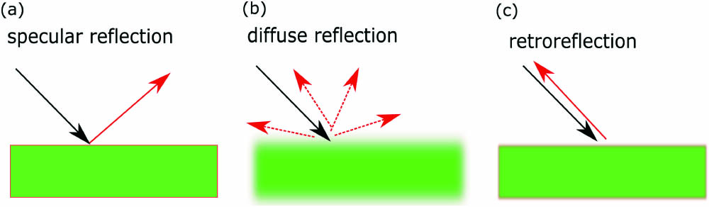
Figure 1.Different types of reflection: (a) specular reflection, (b) diffuse reflection, and (c) retro-reflection.
Two classical methods, designed using geometrical optics, to achieve a retro-reflection are corner-cube reflectors (three mutually perpendicular flat mirrors)[7] and cat’s eyes reflectors (two concentric hemispheres with different radii)[8]. However, for these classical retro-reflectors, the effective working angles are limited, and they are both bulk devices (not easy to integrate practically). In recent years, new ways to achieve a retro-reflection based on an Eaton lens[9] and meta-surfaces have been introduced[10]. An Eaton lens with transmuted singularity can achieve a full-angle (360 deg) retro-reflection[9]. However, it requires inhomogeneous media (refractive index is not constant), and it is still a bulk device (not a compact planar structure). Recently, a planar meta-surface retro-reflector (two cascaded meta-surfaces) has been designed and fabricated[10]. The planar shape of the meta-surface retro-reflector (very thin and lightweight) makes it very easy to integrate with planar modulators. However, its efficiency drops quickly, as the viewing angle changes from 0 deg (nearly 78%) to 50 deg (nearly 16%).
In this study, we design an arbitrary-shaped retro-reflector with high efficiency and wide working angles using a novel theory, optical surface transformation (OST)[11,12], which is a new branch of transformation optics (TO)[13–15] and has been widely applied to various fields in recent years. In TO, a coordinate transformation method is used to design optical devices (transformation media), transforming from the fields and materials in the reference space to the fields and materials in the real space. Many novel optical devices that cannot be designed by traditional methods have been designed by TO, such as invisibility cloaks[13], optical black holes[16], and optical wormholes[17,18]. In recent years, some novel methods based on TO have been proposed to design retro-reflectors[19,20]. However, these TO-based methods require complex mathematical calculations (coordinate transformations and tensor calculations). The required materials designed by TO are complicated (often inhomogeneous, anisotropic, and magnetic). Once a geometrical parameter (shape or size) changes, the devices must be redesigned, and the required materials change correspondingly. OST provides a much simpler way to make designs, in which only the geometrical shape of the device and how to fill the optic-null medium (ONM) inside the device (choosing the appropriate directions of the ONM’s main axes) need to be considered. ONM is also referred to as an optical nihility medium[21,22], which can be treated as a perfect electromagnetic projector/endoscope and has been realized by various methods in microwave[23–29]. Many novel optical devices have been designed by OST (i.e., a geometric surface design method), such as invisibility cloaks[29,30], overlapping illusions without negative refractive index materials[31], open optical resonators[32], beam-amplitude modulators[33], waveguide bends[34], and subwavelength focusing devices[35]. Here, we use OST to design an arbitrarily shaped retro-reflector.
Sign up for Chinese Optics Letters TOC. Get the latest issue of Chinese Optics Letters delivered right to you!Sign up now
The main conclusion in OST is that any two surfaces linked by ONMs perform as equivalent surfaces because they correspond to one common surface in the reference space from the perspective of TO[11,15]. This means that points on these two surfaces have a one-to-one corresponding relation when they are linked by ONMs. The ONM, which is an extremely highly anisotropic medium, has the following relative permittivity and permeability with the main axis along the direction[15]: where diag refers to a diagonal matrix. This expression means that the ONM’s main axis is along the direction. In fact, the ONM’s main axis can be along any other direction and may change its direction inside the device[29–35]. The permittivity and permeability of the ONM are extremely large along its main axis and nearly zero in other orthogonal directions. OST shows that ONM can perform like a highly directional waveguide or perfect endoscope that can project the electromagnetic field distribution along its main axis direction without producing any phase delay and reflection. If two surfaces are linked by ONMs, the electromagnetic field distribution on one surface will be exactly projected onto the other surface. The entire design process consists solely of choosing the geometrical shapes of the devices and figuring out how to design the main axis directions of the ONMs that link the input and output surfaces of the devices[11,12,15,29–35].
We first show how to use this idea to design a half-cylindrical retro-reflector and extend the principle to an arbitrary shape later. Assume the input and output surfaces of our retro-reflector are both planes of the same size [S1 and S2 in Fig. 2(a)]. We can fill the ONM with the main axis along the tangential direction inside a half-cylinder, linking the input and output surfaces of our retro-reflector. We can divide the entire half-cylindrical ONMs into many small fan-shaped regions along the tangential direction. In each small fan-shaped region, its two surfaces are connected by ONM and hence are equivalent surfaces. Such a corresponding relation transfers from one to another, which makes the points on input surface S1 one-to-one, corresponding to the points on the output surface S2. Note that the distribution of points on S1 is reversed by 180 deg compared with those on S2. If a ray is incident onto the input surface S1 with an incident angle , the ONM will guide the ray from one small fan-shaped region to another one with a gradually changing direction of ray. Note that the relative angle between each internal ray and the corresponding equivalent surface is unvaried, and points on S1 and S2 linked by the ONM are reversed by 180 deg. As the result, the direction of the output beam is opposite to that of the incident beam, i.e., reversed by 180 deg (a retro-reflection occurs). Whatever the incident angle , the beam is guided inside the ONM in the same way, and hence the output beam remains opposite of the incident beam.
Figure 2.Schematic diagram using OST to design a retro-reflector. To see the one-to-one corresponding relationship in equivalent surfaces clearly, we use the gradient color to mark each equivalent surface. (a) A half-cylindrical retro-reflector: S1 and S2 are linked by ONMs with axes along the tangential direction. The distribution of the points on S1 and S2 is reversed by 180 deg, and, hence, the output beam is the retro-reflection of the incident beam. (b) A flat planar retro-reflector: ONM with main axis (the purple arrow) along the direction links S1’ and S2’. ONMs with main axis (the purple arrow) along the direction link S1 and S2 with S1’ and S2’, respectively. The directions of purple arrows indicate the directions of the electric field projection during the one-to-one transfer procedure. S1, S2, S1’, and S2’ are all equivalent surfaces. The orientations of corresponding points on S1 and S2 (gradient colored) are reversed by 180 deg.
Another explanation of the retro-reflection phenomenon is from the perspective of the wave vector. Assume the waves impinge on S1 in Fig. 2(a) and are reflected back from S2. We use to denote the parallel component of the wave vectors on S1. Since S1 and S2 are equivalent surfaces (a mirror image), the phases are preserved by point-to-point mapping. Therefore, the parallel component of the wave vectors on S2 is , which guarantees that the reflected waves have reversed direction with respect to the incident waves.
Numerical simulations based on the finite element method (FEM) verify the performance of this half-cylindrical retro-reflector (see Fig. 3). In each subfigure, the oscillating pattern of the field magnitude indicates the standing wave due to the interference between the incident wave and the retro-reflected wave. Note that most structures considered in this study are mirror-symmetric. We only simulate the cases when the incident angle changes from 0 deg to 70 deg, which is mirror-symmetric to the cases when the incident angle changes from 0 deg to .
Figure 3.2D numerical simulation results for the TE polarization wave case. We plot the absolute value of the normalized electric field distribution. The incident wave is a Gaussian beam with waist radius . From (a) to (h), the incident angles change from 0 deg to 70 deg.
Next, we show how to change the geometrical shape of this half-cylindrical retro-reflector to a flat planar retro-reflector. The retro-reflection effect is due to the reverse distribution of points on input and output surfaces linked by ONMs. There are many ways to connect input and output surfaces with ONMs. We can use a combination of ONMs with main axes along the and directions to achieve the same effect [see Fig. 2(b)]. In this case, points on S1 are projected along the direction onto S1’, then projected along the direction onto S2’, and finally projected along the direction onto S2. The distributions of points on S1 and S2 are reversed by 180 deg. The retro-reflection effect can also be expected (see Fig. 4). The key to achieving a retro-reflection effect by OST is to reverse the distributions of points on S1 and S2 by 180 deg. We can also link S1 and S2 using ONMs in various other ways to achieve retro-reflectors of various shapes (see Fig. 5). The effective working angles of our retro-reflector can be further extended to achieve a full-angle (360 deg) retro-reflection by using four isosceles triangular retro-reflectors in Fig. 5(a) back-to-back to form a square. The retro-reflectors designed by our method can also be integrated into an array [see Fig. 5(e)].
Figure 4.2D numerical simulation results for the thin planar retro-reflector as the incident angle changes from (a) 0 deg to (h) 70 deg. The height and width of the planar retro-reflector are and , respectively. The incident wave is a Gaussian beam with waist radius .
Figure 5.2D numerical simulation results for the TE polarization case: we plot the absolute value of the normalized electric field distribution. The white regions are filled by ONMs of various shapes, whose main axis directions are indicated by black arrows. The incident wave is a Gaussian beam with waist radius . The incident angle is 45 deg in all cases except (d). The geometric shapes of the retro-reflectors are (a) an isosceles triangle, (b) a flat triangle, (c), (d) irregular surfaces, and (e) an array of isosceles triangles. Note that the input and the output surfaces can be irregular surfaces as long as they are complementary, which ensures that the phase fronts of the input and output beams are parallel. The input and output surfaces are no longer symmetric, so we simulate 45 deg incidence in (c) and incidence in (d). (e) An array of isosceles triangular retro-reflectors in (a). The retro-reflector can be very thin, e.g., in (f).
Although the geometrical shape of the designed retro-reflector can be changed, the two surfaces S1 and S2 of the designed retro-reflector linked by the ONMs have to be complementary (i.e., S1 and S2 are centrosymmetric about their common point) to ensure that the wave front of the input and output beams are parallel, i.e., no unexpected scatter waves. If the input surface S1 and the output surface S2 of the designed retro-reflector are not centrosymmetric about their common point, the efficiency of the retro-reflector will be influenced (some unexpected scatterings appear).
The flat planar retro-reflector can be designed to be very thin in theory. The key is to keep the reverse one-to-one corresponding relation between the input surface S1 and the output surface S2. Note that the efficiency of our retro-reflector remains very high (nearly 100%), as the incident angle changes from 0 deg to 30 deg. We plot the efficiency of this planar retro-reflector as the incident angle and height change in Figs. 6(a) and 6(b), respectively. The efficiency is defined as the ratio of the power of the retro-reflection to the power of the incident wave. As the incident angle increases, while keeping the waist of the incident Gaussian beam unchanged, the effective illuminated cross section onto our retro-reflector is also increased. The size of the retro-reflector’s surface is fixed during the simulations, which leads to the decrease of the efficiency.
Figure 6.(a) Efficiency of the planar retro-reflector as incident angle changes. (b) Efficiency of the planar retro-reflector as the height changes.
We use micro-channels composed of perfect electrical conductors (PECs) and zero index materials (ZIMs), which have been proposed to realize other ONM-based devices[36–38] to realize the proposed retro-reflector in Fig. 4. The basic diagram is shown in Fig. 7(a), in which the black line segments represent the PECs, and the colored regions represent micro-channels filled with ZIMs ( for the TM wave). Different colors are only used to distinguish each micro-channel, although they use the same material parameters. Different portions of waves can be guided through each micro-channel without changing their phase. We use two-dimensional (2D) simulations to verify the performance of this method; the setups and source (TM wave) are the same as those in Fig. 4. The only difference is that 40 micro-channels replace the ideal ONMs. The amplitude of the electric field for a Gaussian beam with an incident angle of 40 deg is shown in Fig. 7(b). Figure 7(c) shows the efficiency of the retro-reflector with micro-channels for different incident angles, which is worse than the efficiency of the retro-reflector with ideal ONMs in Fig. 6 under large incident angles. The main reason is, for the electric field component polarized in the direction, large impedance mismatch occurs, i.e., the retro-reflector with micro-channels performs as a metal wall. Therefore, the specular reflection in Fig. 1(a) (not retro-reflection) happens in this case, which limits the efficiency of the retro-reflector with micro-channels. The retro-reflector based on micro-channels still achieves high efficiency (over 90% when the incident angles vary between and ). ZIMs can be realized by photonic crystals around the Dirac point frequency[39,40]. The design in Fig. 7 requires ZIMs, which may lead to an extremely narrow working bandwidth. However, this feature (retro-reflection in an extremely narrow working bandwidth and a broadband regular reflection) may also have its special applications, including frequency dependent angle sensing and frequency selective communication. There are also some ways to improve the bandwidth of our retro-reflector by using other structures to realize broadband ONMs[22,25] or using broadband active ZIMs[41].
Figure 7.Realization of the retro-reflector. (a) Basic diagram using micro-channels. (b) 2D numerical simulation results for the TM polarization wave case with an incident angle of 40 deg. (c) Efficiency of the retro-reflector with respect to different incident angles.
Based on OST and ONM, we have proposed a much simpler way to design a retro-reflector. Any two planes linked by ONMs with suitable main axes can perform as a retro-reflector: the distribution of points on one plane is reversed by 180 deg compared with the distribution of points on the other plane from the perspective of one-to-one correspondence in OST. Many retro-reflectors in various shapes have been proposed, including a half-cylinder, a thin planar slab, a flat triangle, and irregular structures. The effective working angles of the retro-reflector can be very large: the efficiency of our retro-reflector is above 98% with incident angles from to and is still above 50% even as the incident angle increases to 80 deg. All retro-reflectors designed by our method only require homogeneous anisotropic media, i.e., ONMs (the orientations of the homogeneous ONM’s main axes may be different). We have also designed micro-channels composed of PECs and ZIMs in microwave frequency to realize the proposed retro-reflector, which may have applications in navigation, sensing, tracking, measurements, and communication systems. The proposed method to design a retro-reflector for electromagnetic waves can also be directly extended to realize a multi-physical retro-reflector that can work for both electromagnetic and acoustic waves.
References
[1] S. G. Turyshev, J. G. Williams, W. M. Folkner, G. M. Gutt, R. T. Baran, R. C. Hein, R. P. Somawardhana, J. A. Lipa, S. Wang. Exp. Astron., 36, 105(2013).
[2] Z. P. Zhang, H. F. Zhang, W. Z. Chen, P. Li, W. D. Meng, Y. M. Wang, J. Wang, W. Hu, F. M. Yang. Adv. Space Res., 54, 811(2014).
[3] D. H. Lee, J. Y. Park. J. Electr. Eng. Technol., 5, 337(2010).
[4] B. Muralikrishnan, S. Phillips, D. Sawyer. Precis. Eng., 44, 13(2016).
[5] R. Ahmed, A. K. Yetisen, S. H. Yun, H. Butt. Light-Sci. Appl., 6, e16214(2017).
[6] H. Do, Y. M. Kim, S. W. Min. Appl. Opt., 58, 2882(2019).
[7] Y. K. Hong, R. R. A. Syms, K. S. J. Pister, L. X. Zhou. J. Micromech. Microeng., 15, 663(2005).
[8] K. H. Chao, B. J. Yang, J. C. Tsai. Opt. Commun., 284, 5221(2011).
[9] Y. G. Ma, C. K. Ong, T. Tyc, U. Leonhardt. Nat. Mater., 8, 639(2009).
[10] E. Arbabi, Y. Horie, S. M. Kamali, A. Faraon. Nat. Photon, 11, 415(2017).
[11] F. Sun, S. He. Sci. Rep., 5, 16032(2015).
[12] F. Sun, S. He. Prog. Electromagn. Res., 151, 169(2015).
[13] J. B. Pendry, D. Schurig, D. R. Smith. Science, 312, 1780(2006).
[14] H. Chen, C. T. Chan, P. Sheng. Nat. Mater., 9, 387(2010).
[15] F. Sun, B. Zheng, H. Chen, W. Jiang, S. Guo, Y. Liu, Y. Ma, S. He. Laser Photon. Rev., 11, 1700034(2017).
[16] D. A. Genov, S. Zhang, X. Zhang. Nat. Phys., 5, 687(2009).
[17] G. Y. Kurylev, M. Lassas, G. Uhlmann. Phys. Rev. Lett., 99, 183901(2007).
[18] F. Sun, Y. Liu, F. Bao, S. He. Opt. Express, 25, 11065(2017).
[19] M. Zedler, G. V. Eleftheriades. Proc. IEEE, 99, 1634(2011).
[20] R. Yang, Z. Y. Lei, J. Fan, D. X. Gao, Z. X. Wang, Y. J. Xie. Europhys. Lett., 104, 24004(2013).
[21] W. Yan, M. Yan, M. Qiu. J. Opt., 13, 024005(2011).
[22] L. Xu, Q. N. Wu, Y. Y. Zhou, H. Y. Chen. Front. Phys., 14, 4251(2019).
[23] Q. He, S. Xiao, X. Li, L. Zhou. Opt. Express, 21, 28948(2013).
[24] B. Zheng, Y. Yang, Z. Shao, Q. Yan, N. H. Shen, L. Shen, H. Wang, E. Li, C. M. Soukoulis, H. Chen. Research, 2019, 8282641(2019).
[25] M. M. Sadeghi, S. Li, L. Xu, B. Hou, H. Chen. Sci. Rep., 5, 8680(2015).
[26] F. Sun, S. Guo, Y. Liu, S. He. Adv. Mater, 30, 1801641(2018).
[27] Y. Zhang, Y. Luo, J. B. Pendry, B. Zhang. Phys. Rev. Lett., 123, 067701(2019).
[28] H. Abdolali, B. Sedeh, M. H. Fakheri. J. Appl. Phys., 127, 054902(2020).
[29] F. Sun, Y. Zhang, J. Evans, S. He. Prog. Electromagn. Res., 165, 107(2019).
[30] F. Sun, S. He. Sci. Rep., 6, 29280(2016).
[31] F. Sun, S. He. Sci. Rep., 6, 19130(2016).
[32] F. Sun, X. Ge, S. He. Sci. Rep., 6, 21333(2016).
[33] S. Guo, F. Sun, S. He. J. Opt. Soc. Am. B, 33, 1847(2016).
[34] F. Sun, S. He. J. Opt. Soc. Am. B, 35, 944(2018).
[35] F. Sun, S. He. Opt. Commun., 427, 139(2018).
[36] M. M. Sadeghi, H. Nadgaran, H. Chen. Front. Phys., 9, 90(2014).
[37] Y. Liu, F. Sun, S. He. Phys. Rev. Appl., 12, 064009(2019).
[38] M. M. Sadeghi. Plasmonics, 15, 709(2019).
[39] X. Huang, Y. Lai, Z. H. Hang, H. Zheng, C. T. Chan. Nat. Mater, 10, 582(2011).
[40] P. Moitra, Y. Yang, Z. Anderson, I. I. Kravchenko, D. P. Briggs, J. Valentine. Nat. Photon, 7, 791(2013).
[41] L. Sun, K. W. Yu. Appl. Phys. Lett., 100, 261903(2012).