
Zhiwei Yang, Xu Wu, Jihong Pei, Shuangchen Ruan. Improvement of bandwidth in a 100 kHz swept laser source with phase controllable signal driving[J]. Chinese Optics Letters, 2023, 21(1): 011407
- Chinese Optics Letters
- Vol. 21, Issue 1, 011407 (2023)
Abstract
1. Introduction
Optical coherence tomography (OCT) is a high-resolution biomedical imaging technique that allows three-dimensional imaging of biological tissues by measuring back-scattered light[1]. The advantages of OCT include high resolution, noninvasiveness, and absence of radiation[2]. Swept source OCT (SS–OCT) is the latest-generation OCT imaging technology, and there have been powerful advances in imaging technology which enable fast imaging speed[3,4]. Swept sources are a key technology for SS-OCT. The primary challenge in SS-OCT is that it requires a high speed, wide wavelength bandwidth, and narrow instantaneous linewidth swept laser source[5,6].
Several authors have studied how to develop high-performance wavelength swept laser sources. In 2006, Huber et al. provided a novel approach for increasing the tuning speed of a swept laser source called the Fourier domain mode locking (FDML) technique[7]. By reducing the dispersion in the fiber delay line of the FDML swept laser source to eliminate intensity noise, the dispersion compensated setup was presented by several groups[8–13]. In order to obtain increased sweep ranges and improve axial resolutions, Marschall et al.[14] used two different amplifiers with complementary characteristics as a gain medium in the resonator. In addition, the combination of two semiconductor optical amplifiers (SOAs) in parallel has been successfully utilized in the swept laser source[15–18], and two SOAs have substantially overlapped in gain spectra. In addition, good roll-off has been demonstrated by several groups[19–21].
However, the previously reported high-performance FDML swept laser sources are all based on the improvement of the performance of optical devices, and there are few articles on improving the performance of device driving. There are also insights inside the swept laser source which can develop a high-speed, wide bandwidth FDML by improving the performance of optical device driving and also reduce significant cavity loss, cost, and complexity.
Sign up for Chinese Optics Letters TOC. Get the latest issue of Chinese Optics Letters delivered right to you!Sign up now
In this paper, we describe the development of a new technique ranging phase controllability as a tool for making a novel driving modulation method of a fiber Fabry–Perot tunable filter (FFP-TF) and demonstrate it for the wide bandwidth of an accessible FDML swept laser. The primary insight that enabled this result is to avoid the discontinuous part of the spectrum by changing the trend of driving voltage value intermittently. A detailed structure framework of phase controllability driving is provided, and the swept laser source achieves broader bandwidth through modulating the driving phase of FFP-TF within the cavity. To the best of our knowledge, the achieved sweep rate of 100.5 kHz and full width at half-maximum (FWHM) bandwidth of 152.25 nm at a center wavelength of 1335.45 nm to the widest bandwidth among swept laser sources using a single SOA at 100 kHz are reported thus far in a 1.3 µm wavelength range. This advance enables high-performance SS-OCT imaging without extra-cavity dispersion compensation, significantly reducing swept source cost and complexity. Our techniques are general and can be applied to swept laser sources and SS-OCT, as well as fiber-optic sensing or interferometric applications.
2. Theoretical Analysis
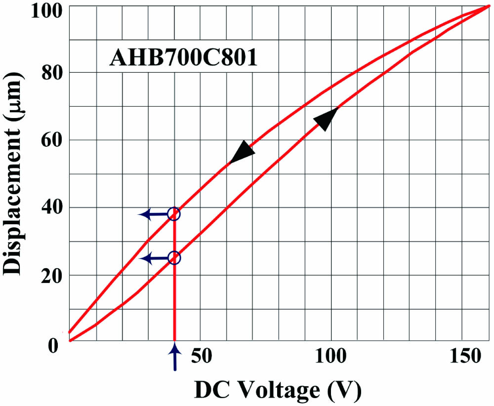
A key component in FFP-TF is piezoelectric ceramics, which will produce different deformations caused by different DC voltages. Due to different deformations of piezoelectric ceramics, the distance between two high-reflection mirrors of FFP-TF is changed, thus filtering out different wavelengths. Figure 1 shows the relationship between deformation displacement and DC voltage of piezoelectric ceramics (AHB700C801). The deformation curve of piezoelectric ceramics is non-overlapping when the voltage increases or decreases and nonlinear. Although the same DC voltage value is used for driving, the deformation displacement of piezoelectric ceramics is different with different DC voltage changing trends (the DC voltage value increases or decreases).
![]()
Figure 1.Relationship between deformation displacement and DC voltage of piezoelectric ceramics.
Figure 2 shows the swept spectrum with respect to different DC voltage values. The driving DC voltage increases from 2 V to 6 V [as shown in Fig. 2(a)], then it decreases from 6 V to 2 V [as shown in Fig. 2(b)], and the swept spectrum is recorded every 1 V. In the same way, the driving DC voltage of FFP-TF is increased from to [as shown in Fig. 2(c)] and then reduced from to [as shown in Fig. 2(d)]. Tables 1 and 2 record the values of the central wavelength under different driving voltages. The center wavelength of the swept output spectra is not constant and changes irregularly even when the driving voltage is the same. The discrete center wavelength of the sweep output is not continuous, and the center wavelength by the values at both ends of the driving voltage range is not within the overall filtering wavelength curve. The same rule applies when the driving voltage is negative.
| The voltage value increases from 2 V to 6 V | |||||
| Voltage/V | 2 | 3 | 4 | 5 | 6 |
| Central wavelength/nm | 1043.95 | 1051.27 | 1059.51 | 1068.27 | 1077.14 |
| The voltage value reduces from 6 V to 2 V | |||||
| Voltage/V | 2 | 3 | 4 | 5 | 6 |
| Central wavelength/nm | 1051.12 | 1060.53 | 1069.78 | 1078.93 | 1087.58 |
Table 1. The Central Wavelength Values at Different DC Voltage
| The voltage value increases from | |||||
| Voltage/V | −2 | −3 | −4 | −5 | −6 |
| Central wavelength/nm | 1113.37 | 1101.9 | 1091.56 | 1080.07 | 1068.22 |
| The voltage value reduces from | |||||
| Voltage/V | −2 | −3 | −4 | −5 | −6 |
| Central wavelength/nm | 1084.16 | 1074.32 | 1063.93 | 1053.82 | 1044.36 |
Table 2. The Central Wavelength Values at Different DC Voltage
![]()
Figure 2.Swept spectrum versus the DC voltage of FFP-TF.
Periodic sinusoidal signal modulation of the FFP-TF has also been utilized for the driving mode of swept laser sources[22–24]. However, through the above analysis of piezoelectric ceramics inside the FFP-TF and the change of the center wavelength of the spectra, we know that the driving of the sinusoidal signal can work normally, but it has some limitations. The key technological challenge is to change the driving trend in the wavelength gap to provide an extended and continuous output spectrum. In order to solve this problem, we propose to change the real-time voltage of the driving of FFP-TF by tuning the phase of the sinusoidal signal. Figure 3 is a schematic showing the concept of the output optical bandwidth in a wavelength swept laser source under the driving modulation method with a standard sinusoidal signal [as shown in Fig. 3(a)] and a phase adjustable sinusoidal signal [as shown in Fig. 3(b)]. With a standard sinusoidal signal [Fig. 3(a)], the rising edge and falling edge are symmetrical. However, due to the fact that the change of central wavelength is not continuous when the FFP-TF is driven by a standard sinusoidal signal, the output optical bandwidth is not fully widened. It is clear that the central wavelength varying trend is consistent with the driving modulation of FFP-TF. The key technological challenges and solutions are changing the driving trend of the segmented wavelength, so the segmented wavelength is spliced with the previous wavelength, and the output spectrum changes continuously and broadens. To match the resolutions, we developed a driving modulation method, which we named ‘phase adjustable sinusoidal signal’ [Fig. 3(b)]. The voltage driving FFP-TF is changed by changing the phase of the sinusoidal signal and broadening the output spectrum. The waveform of the driving of FFP-TF in a single cycle is changed by changing the phase of the sinusoidal signal and broadening the output spectrum. A detailed description of the already driving modulation method designs and results from the feasibility analysis studies performed above is now given in the following.
![]()
Figure 3.Comparison of the (a) spectral range of sinusoidal signal and (b) phase adjustable sinusoidal signal.
3. Experiment and Results
Figure 4 shows a schematic of the block diagram of driving of the phase adjustable sinusoidal signal [as shown in Fig. 4(a)] and the FDML laser resonator [as shown in Fig. 4(b)]. The reference clock (fc) provides the initial frequency to the frequency controller module. Phase tuning is carried out by pressing the key control module, and the results of the accumulator module are processed by the adder module. The waveform controller module controls the frequency and amplitude of the output signal. The digital to analog converter and low-pass filter modules work together to output phase adjustable low-noise analog signals. Figure 4(b) is a schematic of the specific configuration used in this manuscript. The laser oscillator comprised an SOA as broadband gain medium centered at 1320 nm, and the intracavity SOA current and temperature were modulated using a home-built high-precision temperature control driver. An FFP-TF as the tunable, narrowband optical bandpass filter was used. The FFP-TF is driven periodically using a phase adjustable signal generator, and the driving frequency of the tunable wavelength filter is determined by the cavity length. The output sweep signal is detected using a spectral analyzer (from Yokogawa, Inc., AQ6374) to verify the output spectrum of the frequency swept laser source, and a 45 GHz IR photodetector (from New Focus, Inc., Model 1014) and a digital oscilloscope (from Tektronix, Inc., SDA-820Zi-B) at 80 GS/s with 8 bit resolution are used to verify transient intensity profiles.
![]()
Figure 4.Experimental setup: (a) block diagram of driving of the phase adjustable sinusoidal signal; (b) schematic of the FDML swept laser source.
Figure 5 shows the laser output spectra and its transient intensity profiles of the wavelength swept laser sources for using a phase adjustable sinusoidal signal driving waveform. It is important to note that in addition to the sinusoidal signal parameters (frequency, voltage amplitude, voltage offset, and phase), the phase of sinusoidal signal is also necessary in order to generate a broader bandwidth. Output spectra of wavelength swept laser sources are shown in Fig. 5(a). The edge-to-edge tuning range is 152.25 nm from 1259.33 to 1411.58 nm. Figure 5(b) shows transient intensity profiles of the spectrum shown in Fig. 5(a) at a sweeping rate of 100.5 kHz. The transient intensity profiles at both sweep ranges were significantly higher than those within the center because derivatives at the peak and trough of the driving signal were zero, and the deformation of the FFP-TF changed to zero rapidly, while the transmission peak passed through the two ends of the swept range.
![]()
Figure 5.(a) Output spectrum and (b) transient intensity output traces of wavelength swept laser sources.
To characterize the imaging depth of the FDML swept laser source, we tested the performance of the FDML source for OCT imaging in the setup. Figure 6 shows sensitivity roll-off as a function of optical path difference. Sensitivity is measured by placing a partial reflector in the sample arm. The maximum sensitivity of the FDML swept laser source is 40 dB at a depth of 0.25 mm, as shown in Fig. 6. A decrease of approximately 3 dB within a depth range of 2.045 mm is measured.
![]()
Figure 6.SS-OCT point spread functions of a partial reflector placed in the sample arm at different imaging depths.
Figure 7 illustrates the details of one of the point spread functions (PSFs) showing an imaging depth of 0.25 mm for phase adjustable sinusoidal signal operating modes. The measured FWHM resolution of the PSF of the fast Fourier transform (FFT) amplitude fitted by a Gaussian function was 6.5 µm in air. It corresponds to the effective axial resolution of in tissue ().
![]()
Figure 7.Detail of the PSF showing an imaging depth of 0.25 mm.
4. Conclusion
In conclusion, we presented a new driving modulation method of FFP-TF, the ranging phase controllability. This technique has numerous advantages over previously described bandwidth widening techniques. First, it is very power efficient, the driving voltage of the FFP-TF is changed by adjusting the phase of the driving signal, and the change of bandwidth can be seen in real time. In addition, this approach improves the effective swept bandwidth through optimizing the driving circuit of FFP-TF without the need for extra-cavity dispersion compensation, significantly reducing system cost and complexity. Our work also provides new general insights into advanced problems associated with high-performance swept source lasers. All of our techniques are general, and we firmly believe that this work would be beneficial to the OCT society, but also more generally to fiber-optic sensing or interferometric applications.
References
[1] D. Huang, E. A. Swanson, C. P. Lin, J. S. Schuman, W. G. Stinson, W. Chang, M. R. Hee, T. Flotte, K. Gregory, C. A. Puliafito, A. Et. Optical coherence tomography. Science, 254, 1178(1991).
[2] T. Klein, R. Huber. High-speed OCT light sources and systems [Invited]. Biomed. Opt. Express, 8, 828(2017).
[3] T. Wu, Z. Ding, K. Wang, L. Xu, M. Chen, C. Wang. Swept source optical coherence tomography based on scanning fiber probe. Chin. Opt. Lett., 29, 37(2009).
[4] T. Wu, Y. Liu. Optimal non-uniform fast Fourier transform for high-speed swept source optical coherence tomography. Chin. Opt. Lett., 11, 021702(2013).
[5] M. Chen, Z. Ding, L. Xu, T. Wu, C. Wang, G. Shi, Y. Zhang. All-fiber ring-cavity based frequency swept laser source for frequency domain OCT. Chin. Opt. Lett., 8, 202(2010).
[6] M. F. Shirazi, M. Jeon, J. Kim. 850 nm centered wavelength-swept laser based on a wavelength selection Galvo filter. Chin. Opt. Lett., 14, 011401(2016).
[7] R. Huber. Fourier domain mode locking (FDML): a new laser operating regime and applications for biomedical imaging, profilometry, ranging and sensing. Opt. Express, 14, 3225(2006).
[8] D. C. Adler, W. Wieser, F. Trepanier, J. M. Schmitt, R. A. Huber. Extended coherence length Fourier domain mode locked lasers at 1310 nm. Opt. Express, 19, 20930(2011).
[9] A. Takada, M. Fujino, S. Nagano. Dispersion dependence of linewidth in actively mode-locked ring lasers. Opt. Express, 20, 8310(2011).
[10] W. Wieser, T. Klein, D. C. Adler, F. Trépanier, C. M. Eigenwillig, S. Karpf, J. M. Schmitt, R. Huber. Extended coherence length megahertz FDML and its application for anterior segment imaging. Biomed. Opt. Express, 3, 2647(2012).
[11] N. Lippok, S. Coen, P. Nielsen, F. Vanholsbeeck. Dispersion compensation in Fourier domain optical coherence tomography using the fractional Fourier transform. Opt. Express, 20, 23398(2012).
[12] S. Tozburun, M. Siddiqui, B. J. Vakoc. 14-A rapid, dispersion-based wavelength-stepped and wavelength-swept laser for optical coherence tomography. Opt. Express, 22, 3414(2014).
[13] T. Pfeiffer, M. Petermann, W. Draxinger, C. Jirauschek, R. Huber. Ultra low noise Fourier domain mode locked laser for high quality megahertz optical coherence tomography. Biomed. Opt. Express, 9, 4130(2018).
[14] S. Marschall, T. Klein, W. Wieser, B. R. Biedermann, K. Hsu, K. P. Hansen, B. Sumpf, K.-H. Hasler, G. Erbert, O. B. Jensen, C. Pedersen, R. Huber, P. E. Andersen. Fourier domain mode-locked swept source at 1050 nm based on a tapered amplifier. Opt. Express, 18, 15820(2010).
[15] W. Y. Oh, S. H. Yun, G. J. Tearney, B. E. Bouma. Wide tuning range wavelength-swept laser with two semiconductor optical amplifiers. IEEE Photon. Technol. Lett., 17, 678(2005).
[16] M. Yong Jeon, J. Zhang, Q. Wang, Z. Chen, D. Huang, E. A. Swanson, C. P. Lin, J. S. Schuman, W. G. Stinson, W. Chang, M. R. Hee, T. Flotte, K. Gregory, C. A. Puliafito, J. G. Fujimoto, R. Huber, M. Wojtkowski, K. Taira, K. Hsu, W. Jenkins, D. C. Adler, M. Gargesha, F. Rothenberg, J. Belding, M. Watanabe, D. L. Wilson, A. M. Rollins, Y. Chen, J. Schmitt, J. Connolly, V. J. Srinivasan. High-speed and wide bandwidth Fourier domain mode-locked wavelength swept laser with multiple SOAs. Opt. Express, 16, 2547(2008).
[17] W. Jang, J. Lim, H. Kim, J. Ha. Broadband wavelength swept source combining a quantum dot and a quantum well SOA in the wavelength range of 1153–1366 nm. Electron. Lett., 49, 1205(2013).
[18] S. H. Kassani, M. Villiger, N. Uribe-Patarroyo, C. Jun, R. Khazaeinezhad, N. Lippok, B. E. Bouma. Extended bandwidth wavelength swept laser source for high resolution optical frequency domain imaging. Opt. Express, 25, 8255(2017).
[19] B. Potsaid, B. Baumann, D. Huang, S. Barry, A. E. Cable, J. S. Schuman, J. S. Duker, J. G. Fujimoto. Ultrahigh speed 1050 nm swept source/Fourier domain OCT retinal and anterior segment imaging at 100,000 to 400,000 axial scans per second. Opt. Express, 18, 20029(2010).
[20] V. Jayaraman, J. Jiang, B. Potsaid, G. Cole, J. Fujimoto, A. Cable. Design and performance of broadly tunable, narrow line-width, high repetition rate 1310 nm VCSELs for swept source optical coherence tomography. Proc. SPIE, 8276, 82760D(2012).
[21] V. Jayaraman, J. Jiang, H. Li, P. J. S. Heim, G. D. Cole, B. Potsaid, J. G. Fujimoto, A. Cable. OCT imaging up to 760 kHz axial scan rate using single-mode 1310 nm MEMS-tunable VCSELs with >100 nm tuning range. CLEO: Science and Innovations(2011).
[22] R. Huber, D. C. Adler, V. J. Srinivasan, J. G. Fujimoto. Fourier domain mode locking at 1050 nm for ultra-high-speed optical coherence tomography of the human retina at 236,000 axial scans per second. Opt. Lett., 32, 2049(2007).
[23] E. J. Jung, C.-S. Kim, M. Y. Jeong, M. K. Kim, M. Y. Jeon, W. Jung, Z. Chen. Characterization of FBG sensor interrogation based on a FDML wavelength swept laser. Opt. Express, 16, 16552(2008).
[24] T. Klein, W. Wieser, B. R. Biedermann, C. M. Eigenwillig, G. Palte, R. Huber. Raman-pumped Fourier-domain mode-locked laser: analysis of operation and application for optical coherence tomography. Opt. Lett., 33, 2815(2008).

Set citation alerts for the article
Please enter your email address
© Copyright 2018-2021 | Chinese Laser Press. All Rights Reserved 沪ICP备15018463号-20