• Photonics Research
  • Vol. 9, Issue 6, 944 (2021)
Yao Huang1, Jingjing Zhang2、7、*, Jinhui Zhou3, Bo Qiang1, Zhengji Xu4, Lin Liu1, Jifang Tao5, Nicolas Kossowski1, Qijie Wang1、6、8、*, and Yu Luo1、9、*
Author Affiliations
  • 1School of Electrical and Electronic Engineering, Nanyang Technological University, Singapore 639798, Singapore
  • 2State Key Laboratory of Millimeter Waves, Southeast University, Nanjing 210096, China
  • 3Electrical Engineering, Kulicke & Soffa Pte. Ltd., Singapore 554369, Singapore
  • 4School of Microelectronics Science and Technology, Sun Yat-sen University, Zhuhai 519082, China
  • 5School of Information and Engineering, Shandong University, Qingdao 266237, China
  • 6School of Physical and Mathematical Sciences, Nanyang Technological University, Singapore 637371, Singapore
  • 7e-mail: zhangjingjing@seu.edu.cn
  • 8e-mail: qjwang@ntu.edu.sg
  • 9e-mail: luoyu@ntu.edu.sg
  • show less
    DOI: 10.1364/PRJ.414437 Cite this Article Set citation alerts
    Yao Huang, Jingjing Zhang, Jinhui Zhou, Bo Qiang, Zhengji Xu, Lin Liu, Jifang Tao, Nicolas Kossowski, Qijie Wang, Yu Luo. Polarization-robust mid-infrared carpet cloak with minimized lateral shift[J]. Photonics Research, 2021, 9(6): 944 Copy Citation Text show less
    Light ray tracing for a conformal carpet cloak with minimized lateral shift. The carpet cloak covers the top of a curved PEC bump, making it reflect light as a virtual flat plane denoted by the blue dashed line. The blue and black solid arrows indicate the trajectories of light reflected by the virtual plane and the cloak, respectively. The contour plot represents the refractive index distribution for the cloak. The cloak is designed with a conformal transformation with a=0.005, b=0.005, and t=3.7.
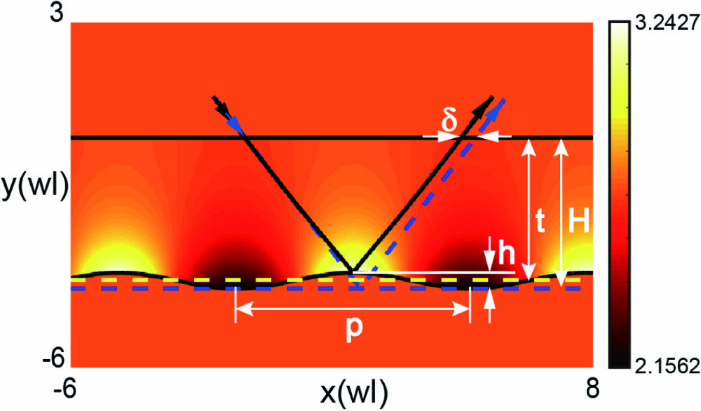
    Fig. 1. Light ray tracing for a conformal carpet cloak with minimized lateral shift. The carpet cloak covers the top of a curved PEC bump, making it reflect light as a virtual flat plane denoted by the blue dashed line. The blue and black solid arrows indicate the trajectories of light reflected by the virtual plane and the cloak, respectively. The contour plot represents the refractive index distribution for the cloak. The cloak is designed with a conformal transformation with a=0.005, b=0.005, and t=3.7.
    Minimization of the lateral shift. Analytically calculated lateral shift and simulated reflection coefficients (for TE and TM polarizations) at the interface between the background and the cloak as a function of (a) the periodicity p and (b) the cloak height H.
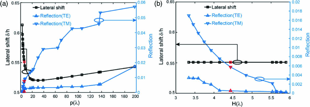
    Fig. 2. Minimization of the lateral shift. Analytically calculated lateral shift and simulated reflection coefficients (for TE and TM polarizations) at the interface between the background and the cloak as a function of (a) the periodicity p and (b) the cloak height H.
    Numerical verification of the polarization-insensitive performance. Simulated electric field distributions of a bumped surface (a) without the cloak and (b) with the cloak when a TE-polarized Gaussian beam is incident at an angle 32° with respect to the horizontal direction. Simulated electric field distributions of a bumped surface (c) without the cloak and (d) with the cloak when a TE-polarized Gaussian beam is incident at an angle 42° with respect to the horizontal direction. Simulated magnetic field distributions of a bumped surface (e) without the cloak and (f) with the cloak when a TM-polarized Gaussian beam is incident at an angle 32° with respect to the horizontal direction. Simulated magnetic field distributions of a bumped surface (g) without the cloak and (h) with the cloak when a TM-polarized Gaussian beam is incident at an angle 42° with respect to the horizontal direction.
    Fig. 3. Numerical verification of the polarization-insensitive performance. Simulated electric field distributions of a bumped surface (a) without the cloak and (b) with the cloak when a TE-polarized Gaussian beam is incident at an angle 32° with respect to the horizontal direction. Simulated electric field distributions of a bumped surface (c) without the cloak and (d) with the cloak when a TE-polarized Gaussian beam is incident at an angle 42° with respect to the horizontal direction. Simulated magnetic field distributions of a bumped surface (e) without the cloak and (f) with the cloak when a TM-polarized Gaussian beam is incident at an angle 32° with respect to the horizontal direction. Simulated magnetic field distributions of a bumped surface (g) without the cloak and (h) with the cloak when a TM-polarized Gaussian beam is incident at an angle 42° with respect to the horizontal direction.
    Blueprint of the mid-IR carpet cloak designed at a wavelength λ=10.6 μm. (a) Schematic of the practical implementation of the cloak. Light is incident upon a triangular background drilled with homogenous holes. The cloak is built by drilling spatially gradient holes into an SOI wafer. Magnetic field distributions when a TM-polarized Gaussian beam is incident at an angle 45° onto (b) a bare bump and (c) a bumped surface covered with the cloak.
    Fig. 4. Blueprint of the mid-IR carpet cloak designed at a wavelength λ=10.6  μm. (a) Schematic of the practical implementation of the cloak. Light is incident upon a triangular background drilled with homogenous holes. The cloak is built by drilling spatially gradient holes into an SOI wafer. Magnetic field distributions when a TM-polarized Gaussian beam is incident at an angle 45° onto (b) a bare bump and (c) a bumped surface covered with the cloak.
    Demonstration of the robust cloaking performance over a broad frequency range from 24 to 29 THz. (a) Intensity profile versus the different positions along the white dashed line in Fig. 4(b) when the incident laser beam illuminates the bare bump. (b) Intensity profile versus the different positions along the white dashed line in Fig. 4(c) when the incident laser beam illuminates the bump covered with the cloak.
    Fig. 5. Demonstration of the robust cloaking performance over a broad frequency range from 24 to 29 THz. (a) Intensity profile versus the different positions along the white dashed line in Fig. 4(b) when the incident laser beam illuminates the bare bump. (b) Intensity profile versus the different positions along the white dashed line in Fig. 4(c) when the incident laser beam illuminates the bump covered with the cloak.
    Yao Huang, Jingjing Zhang, Jinhui Zhou, Bo Qiang, Zhengji Xu, Lin Liu, Jifang Tao, Nicolas Kossowski, Qijie Wang, Yu Luo. Polarization-robust mid-infrared carpet cloak with minimized lateral shift[J]. Photonics Research, 2021, 9(6): 944
    Download Citation