
Yao Huang, Jingjing Zhang, Jinhui Zhou, Bo Qiang, Zhengji Xu, Lin Liu, Jifang Tao, Nicolas Kossowski, Qijie Wang, Yu Luo. Polarization-robust mid-infrared carpet cloak with minimized lateral shift[J]. Photonics Research, 2021, 9(6): 944
- Photonics Research
- Vol. 9, Issue 6, 944 (2021)
Abstract
1. INTRODUCTION
Invisibility cloaks, originally existing in scientific fiction and movies, have attracted people’s interest for centuries. For military applications, they can be used as stealth coating to conceal tanks, aircrafts, submarines, and so on. For commercial applications, they can be used to prevent unwanted scattering from defects in antennas, lasers, electronic circuits, and so on. The recent development of transformation optics and metamaterials greatly promotes the experimental realization of cloaking devices [1–10]. As theoretically demonstrated by Pendry and coworkers in 2006, ideal invisibility cloaks in free space generally require near-zero permittivity/permeability components. Although several types of such cloaks have been experimentally implemented in the microwave regime [11,12], the resonant elements involved (to realize near-zero permittivity or permeability) greatly limit their bandwidths. To tackle this problem, Li and Pendry proposed the concept of a “carpet” cloak, which, instead of transparentizing the hidden object, makes it reflect light as a flat surface [13]. Since carpet cloaks no longer require near-zero value in permittivity or permeability, they have the intrinsic advantages of lower dissipation loss and broader working bandwidth as compared with free-space cloaks [13]. Under optical surface transformation, the optic-null medium helps to build a wide-illumination range and low-loss invisibility cloak, while it only works under TM polarization [14].
In general, carpet cloaks can be designed using either quasi-conformal mapping or bilinear transformation [15]. Earlier experimental realizations of carpet cloaks are generally based on quasi-conformal mappings [16–19]. This type of carpet cloaks operates on inhomogeneous refractive index and works for unpolarized light as demonstrated at both microwave [20] and optical frequencies [21]. However, the approximation made in quasi-conformal mapping leads to a lateral shift of the reflected light beam, whose value is comparable to the dimension of the hidden object, and hence makes the object detectable [22]. On the other hand, carpet cloaks designed with bilinear transformation make use of several birefringent crystals judiciously glued together [23,24]. This type of cloak eliminates the lateral shift, but it only works for a specific light polarization. Recently, with the advent of metasurfaces, an ultrathin carpet cloak design was proposed. By judiciously designing the meta-atoms to achieve the required phase shift and restore the phase front, the full-polarization metasurface-based skin cloak has been realized [25]. In addition, the tunable metasurface illusion device can be constructed by applying programmable voltage source to adjust the varactor configurations on the metasurface [26]. However, these metasurface cloak designs have limited working bandwidths. Up to now, the design and implementation of a broadband carpet cloak that is polarization insensitive while addressing the problem of lateral shift are still challenging.
In this paper, we attempt to tackle the two problems mentioned above simultaneously. We target at mid-infrared (IR) frequency range, owing to its wide application in military and industry, such as semiconductor processing, spectroscopy, chemical and biomolecular sensing, and security. Many mid-IR devices have been proposed and implemented, including lasers [27,28], sensors [29,30], and frequency combs [31]. However, to the best of our knowledge, an invisibility cloak has never been realized in this frequency range [32–40]. Our approach makes use of a judiciously designed conformal mapping, and the resultant carpet cloak relies only on an isotropic nonresonant medium. Moreover, our carpet cloak design is based on commercially available silicon-on-insulator (SOI) wafers and is suitable for mass production of on-chip cloaking devices.
Sign up for Photonics Research TOC. Get the latest issue of Photonics Research delivered right to you!Sign up now
2. RESULTS AND DISCUSSION
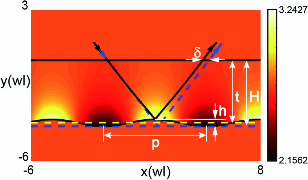
Figure 1.Light ray tracing for a conformal carpet cloak with minimized lateral shift. The carpet cloak covers the top of a curved PEC bump, making it reflect light as a virtual flat plane denoted by the blue dashed line. The blue and black solid arrows indicate the trajectories of light reflected by the virtual plane and the cloak, respectively. The contour plot represents the refractive index distribution for the cloak. The cloak is designed with a conformal transformation with
According to the theory of transformation optics, light reflected from the bump surface covered with the cloak will propagate in exactly the same way as the reflected beam from a planar surface. The transformation parameters , , and control the shape of the bumps (e.g., height of bumps ) as well as the range of refractive indices of the cloak (e.g., minimum and maximum values of refractive indices) according to
In principle, , , and can be arbitrary positive values but must be judiciously designed in order to make the implementation of the cloak experimentally feasible. In our design, these parameters are chosen as , , and to hide high bumps in a background with a refractive index . The corresponding refractive indices of the cloak range from 2.1562 to 3.2427. As depicted by the contour plot in Fig. 1, the minimum and the maximum refractive indices occur at the valleys and the peaks of the bumps, respectively. Away from the bumps, the cloak index gradually changes to (i.e., he background index), fulfilling the condition of impedance match.
We analytically retrieve and compare the light trajectories in the systems of a cloak and a virtual slab as shown in Fig. 1. In the cloak system, the ray position vector is obtained by solving a differential eikonal equation [42]
In the system of a virtual slab, the reflecting plane denoted by the blue dashed line is located at the bottom of the cloak. The thickness of this virtual slab equals the height of the cloak indicated by . The ray diagram presented in Fig. 1 clearly shows the lateral shift between the reflected light ray from the cloaked bumps and that from a flat perfect electric conductor (PEC) plane [44–46]. The lateral shift results from the nonzero value of , i.e., height difference between the equivalent reflection plane of the cloak (yellow dashed plane) and the virtual reflection plane of the slab (blue dashed plane). Mathematically, takes the following form:
![]()
Figure 2.Minimization of the lateral shift. Analytically calculated lateral shift and simulated reflection coefficients (for TE and TM polarizations) at the interface between the background and the cloak as a function of (a) the periodicity
![]()
Figure 3.Numerical verification of the polarization-insensitive performance. Simulated electric field distributions of a bumped surface (a) without the cloak and (b) with the cloak when a TE-polarized Gaussian beam is incident at an angle 32° with respect to the horizontal direction. Simulated electric field distributions of a bumped surface (c) without the cloak and (d) with the cloak when a TE-polarized Gaussian beam is incident at an angle 42° with respect to the horizontal direction. Simulated magnetic field distributions of a bumped surface (e) without the cloak and (f) with the cloak when a TM-polarized Gaussian beam is incident at an angle 32° with respect to the horizontal direction. Simulated magnetic field distributions of a bumped surface (g) without the cloak and (h) with the cloak when a TM-polarized Gaussian beam is incident at an angle 42° with respect to the horizontal direction.
To test the cloak performance for TM polarization, we plot the magnetic field distributions in Figs. 3(e)–3(h) when the polarization of the incident Gaussian beam is switched to TM. As expected, the scattering produced by the bumped surface in Figs. 3(e) and 3(g) is eliminated by the carpet cloak in Figs. 3(f) and 3(h), respectively. Considering the generality of our conformal transformation approach, this minimized lateral shift polarization-robust carpet cloak can be implemented in any frequency range with a proper choice of the material.
![]()
Figure 4.Blueprint of the mid-IR carpet cloak designed at a wavelength
The required refractive index distribution of the cloak can be realized by drilling subwavelength holes with different radii into the silicon device layer at a fixed periodicity. As mentioned before, the refractive index of the background medium in our design is set as , and the refractive index distributions of the cloak span from 2.1562 to 3.2427 as shown in Fig. 1. We use the following equation to deduce the hole radius distribution for the whole device:
The commercial software CST Microwave Studio is used to examine the performance of the cloak implemented on the SOI wafer. The refractive indices of silicon and silica are taken from Ref. [47] and Ref. [48], respectively. Figures 4(b) and 4(c) plot the magnetic field intensities at the top plane of the silicon device layer when a Gaussian beam is incident upon (1) a bare bump and (2) a bump surface covered by the cloak. Through the comparison, we can observe remarkable scattering from the bare bump, whereas such scattering is dramatically suppressed by the presence of the cloak, giving rise to a single reflection profile. In other words, the cloak has successfully concealed the curved bump, making it reflect light as a flat PEC plane. Moreover, the suppressed scattering is observed for arbitrary incident angles, verifying the excellent performance of the cloak implemented on the SOI wafer. Since light will never penetrate into the PEC bump, any object could be hidden behind the bump and appear invisible to the observers outside.
![]()
Figure 5.Demonstration of the robust cloaking performance over a broad frequency range from 24 to 29 THz. (a) Intensity profile versus the different positions along the white dashed line in Fig.
3. CONCLUSION
In conclusion, we propose a mid-IR carpet cloak based on a judiciously designed conformal transformation. This cloak operates on isotropic refractive index, which can be easily implemented with nonresonant structures. Analytical calculations and numerical simulations show that through properly choosing the periodicity and increasing the cloak height , the lateral shift can be effectively minimized with the reflection controlled. The polarization-robust performance over a broadband frequency range is also demonstrated. The practical implementation of this cloak can be realized on the platform of commercially available SOI wafers by drilling spatially gradient holes with judiciously designed radii into the silicon layer. Our conformal transformation approach not only provides an alternative solution for cloak design but also offers a general platform for the design of other optical devices such as lenses, waveguides, and optical cavities.
References
[1] A. J. Ward, J. B. Pendry. Refraction and geometry in Maxwell’s equations. J. Mod. Opt., 43, 773-793(1996).
[2] U. Leonhardt. Optical conformal mapping. Science, 312, 1777-1780(2006).
[3] H. Chen, B. I. Wu, B. Zhang, J. A. Kong. Electromagnetic wave interactions with a metamaterial cloak. Phys. Rev. Lett., 99, 063903(2007).
[4] H. Chen, C. T. Chan, P. Sheng. Transformation optics and metamaterials. Nat. Mater., 9, 387-396(2010).
[5] Y. Liu, X. Zhang. Recent advances in transformation optics. Nanoscale, 4, 5277-5292(2012).
[6] T. Han, X. Bai, D. Gao, J. T. L. Thong, B. Li, C. W. Qiu. Experimental demonstration of a bilayer thermal cloak. Phys. Rev. Lett., 112, 054302(2014).
[7] J. Y. H. Teo, L. J. Wong, M. C. Molardi, P. Genevet. Controlling electromagnetic fields at boundaries of arbitrary geometries. Phys. Rev. A, 94, 023820(2016).
[8] H. Chu, Q. Li, B. Liu, J. Luo, S. Sun, Z. H. Hang, L. Zhou, Y. Lai. A hybrid invisibility cloak based on integration of transparent metasurfaces and zero-index materials. Light Sci. Appl., 7, 50(2018).
[9] J. Zhang, J. B. Pendry, Y. Luo. Transformation optics from macroscopic to nanoscale regimes: a review. Adv. Photon., 1, 014001(2019).
[10] E. Bor, U. G. Yasa, H. Kurt, M. Turduev. Demonstration of carpet cloaking by an anisotropic zero refractive index medium. Opt. Lett., 45, 2423-2426(2020).
[11] J. B. Pendry, D. Schurig, D. R. Smith. Controlling electromagnetic fields. Science, 312, 1780-1782(2006).
[12] D. Schurig, J. J. Mock, B. J. Justice, S. A. Cummer, J. B. Pendry, A. F. Starr, D. R. Smith. Metamaterial electromagnetic cloak at microwave frequencies. Science, 314, 977-980(2006).
[13] J. Li, J. B. Pendry. Hiding under the carpet: a new strategy for cloaking. Phys. Rev. Lett., 101, 203901(2008).
[14] F. Sun, Y. Zhang, J. Evans, S. He. A camouflage device without metamaterials. Prog. Electromagn. Res., 165, 107-117(2019).
[15] F. Liu, J. Li, J. Zhang, Y. Luo. World Scientific Handbook of Metamaterials and Plasmonics, 2(2017).
[16] J. Valentine, J. Li, T. Zentgraf, G. Bartal, X. Zhang. An optical cloak made of dielectrics. Nat. Mater., 8, 568-571(2009).
[17] T. Ergin, N. Stenger, P. Brenner, J. B. Pendry, M. Wegener. Three-dimensional invisibility cloak at optical wavelengths. Science, 328, 337-339(2010).
[18] T. Ergin, J. Fischer, M. Wegener. Detailed optical characterization of three-dimensional visible-frequency polarization-independent carpet invisibility cloak. Phys. B Condens. Matter, 407, 4075-4077(2012).
[19] N. Wang, Y. Ma, R. Huang, C. K. Ong. Far field free-space measurement of three dimensional hole-in-teflon invisibility cloak. Opt. Express, 21, 5941-5948(2013).
[20] H. F. Ma, T. J. Cui. Three-dimensional broadband ground-plane cloak made of metamaterials. Nat. Commun., 1, 21(2010).
[21] M. Gharghi, C. Gladden, T. Zentgraf, Y. Liu, X. Yin, J. Valentine, X. Zhang. A carpet cloak for visible light. Nano Lett., 11, 2825-2828(2011).
[22] B. Zhang, T. Chan, B.-I. Wu. Lateral shift makes a ground-plane cloak detectable. Phys. Rev. Lett., 104, 233903(2010).
[23] X. Chen, Y. Luo, J. Zhang, K. Jiang, J. B. Pendry, S. Zhang. Macroscopic invisibility cloaking of visible light. Nat. Commun., 2, 176(2011).
[24] D. C. Liang, J. Q. Gu, J. G. Han, Y. M. Yang, S. Zhang, W. L. Zhang. Robust large dimension terahertz cloaking. Adv. Mater., 24, 916-921(2012).
[25] Y. Yang, L. Jing, B. Zheng, R. Hao, W. Yin, E. Li, C. M. Soukoulis, H. Chen. Full-polarization 3D metasurface cloak with preserved amplitude and phase. Adv. Mater., 28, 6866-6871(2016).
[26] C. Huang, J. Yang, X. Wu, J. Song, M. Pu, C. Wang, X. Luo. Reconfigurable metasurface cloak for dynamical electromagnetic illusions. ACS Photon., 5, 1718-1725(2017).
[27] P. A. Budni, L. A. Pomeranz, M. L. Lemons, C. A. Miller, J. R. Mosto, E. P. Chicklis. Efficient mid-infrared laser using 1.9-μm-pumped Ho:YAG and ZnGeP2 optical parametric oscillators. J. Opt. Soc. Am. B., 17, 723-728(2000).
[28] R. W. Waynant, I. K. Ilev, I. Gannot. Mid-infrared laser applications in medicine and biology. Philos. Trans. R. Soc. A, 359, 635-644(2001).
[29] T. Töpfer, K. P. Petrov, Y. Mine, D. Jundt, R. F. Curl, F. K. Tittel. Room-temperature mid-infrared laser sensor for trace gas detection. Appl. Opt., 36, 8042-8049(1997).
[30] P. Werle, F. Slemr, K. Maurer, R. Kormann, R. Mucke, B. Janker. Near- and mid-infrared laser-optical sensors for gas analysis. Opt. Laser Eng., 37, 101-114(2002).
[31] A. Schliesser, N. Picqué, T. W. Hansch. Mid-infrared frequency combs. Nat. Photonics, 6, 440-449(2012).
[32] L. H. Gabrielli, J. Cardenas, C. B. Poitras, M. Lipson. Silicon nanostructure cloak operating at optical frequencies. Nat. Photonics, 3, 461-463(2009).
[33] H. F. Ma, W. X. Jiang, X. M. Yang, X. Y. Zhou, T. J. Cui. Compact-sized and broadband carpet cloak and free-space cloak. Opt. Express, 17, 19947-19959(2009).
[34] R. Liu, C. Ji, J. J. Mock, J. Y. Chin, T. J. Cui, D. R. Smith. Broadband ground-plane cloak. Science, 323, 366-369(2009).
[35] V. A. Tamma, J. Blair, C. J. Summers, W. Park. Dispersion characteristics of silicon nanorod based carpet cloaks. Opt. Express, 18, 25746-25756(2010).
[36] J. Zhang, L. Liu, Y. Luo, S. Zhang, N. A. Mortensen. Homogeneous optical cloak constructed with uniform layered structures. Opt. Express, 19, 8625-8631(2011).
[37] F. Zhou, Y. Bao, W. Cao, C. T. Stuart, J. Gu, W. Zhang, C. Sun. Hiding a realistic object using a broadband terahertz invisibility cloak. Sci. Rep., 1, 78(2011).
[38] B. Zhang, Y. Luo, X. Liu, G. Barbastathis. Macroscopic invisibility cloak for visible light. Phys. Rev. Lett., 106, 033901(2011).
[39] M. Yin, X. Y. Tian, H. X. Han, D. C. Li. Free-space carpet-cloak based on gradient index photonic crystals in metamaterial regime. Appl. Phys. Lett., 100, 124101(2012).
[40] G. Scherrer, M. Hofman, M. K. Wojtek Smigaj, T.-M. Chang, D. L. Xavier Melique, O. Vanbesien, B. Cluzel, F. D. Fornel, S. Guenneau, B. Gralak. Photonic crystal carpet: manipulating wave fronts in the near field at 1.55 μm. Phys. Rev. B, 88, 115110(2013).
[41] M. Kraft, Y. Luo, S. A. Maier, J. B. Pendry. Designing plasmonic gratings with transformation optics. Phys. Rev. X, 5, 031029(2015).
[42] M. Born, E. Wolf. Principles of Optics, 109-127(1980).
[43] B. Richerzhagen. Finite element ray tracing: a new method for ray tracing in gradient-index media. Appl. Opt., 35, 6186-6189(1996).
[44] Z. L. Mei, J. Bai, T. J. Cui. Illusion devices with quasi-conformal mapping. J. Electromagn. Waves Appl., 24, 2561-2573(2010).
[45] J. H. Lee, J. Blair, V. A. Tamma, Q. Wu, S. J. Rhee, C. J. Summers, W. Park. Direct visualization of optical frequency invisibility cloak based on silicon nanorod array. Opt. Express, 17, 12922-12928(2009).
[46] D. Shin, Y. Urzhumov, Y. Jung, G. Kang, S. Baek, M. Choi, H. Park, K. Kim, D. R. Smith. Broadband electromagnetic cloaking with smart metamaterials. Nat. Commun., 3, 1213(2012).
[47] D. F. Edwards, E. Ochoa. Infrared refractive index of silicon. Appl. Opt., 19, 4130-4131(1980).
[48] J. Kischkat, S. Peters, B. Gruska, M. Semtsiv, M. Chashnikova, M. Klinkmüller, O. Fedosenko, S. Machulik, A. Aleksandrova, G. Monastyrskyi, Y. Flores, W. T. Masselink. Mid-infrared optical properties of thin films of aluminum oxide, titanium dioxide, silicon dioxide, aluminum nitride, and silicon nitride. Appl. Opt., 51, 6789-6798(2012).

Set citation alerts for the article
Please enter your email address
© Copyright 2018-2021 | Chinese Laser Press. All Rights Reserved 沪ICP备15018463号-20