• Photonics Research
  • Vol. 9, Issue 2, 88 (2021)
He Wen1、*, Yuanhang Zhang1, Rachel Sampson1, Nicolas K. Fontaine2, Ning Wang1, Shengli Fan1, and Guifang Li1
Author Affiliations
  • 1CREOL, The College of Optics & Photonics, University of Central Florida, Orlando, Florida 32816-2700, USA
  • 2Bell Laboratories, Alcatel-Lucent, Holmdel, New Jersey 07733, USA
  • show less
    DOI: 10.1364/PRJ.411529 Cite this Article Set citation alerts
    He Wen, Yuanhang Zhang, Rachel Sampson, Nicolas K. Fontaine, Ning Wang, Shengli Fan, Guifang Li. Scalable non-mode selective Hermite–Gaussian mode multiplexer based on multi-plane light conversion[J]. Photonics Research, 2021, 9(2): 88 Copy Citation Text show less
    Hadamard-coded MPLC-based NMS mux for 16 HG modes. (a) Input array; (b) the HG mode set that can be generated using this NMS mux; (c) the input array coded to produce (d) the desired output HG0,0 mode; (e) the input array coded to produce (f) the desired output HG0,1 mode; (g) the input array coded to produce (h) the desired output HG3,2 mode. The locations of the zero crossings, where the adjacent spots change from negative to positive or vice versa, are identical for the input array and output modes, and they are marked by arrows. This similarity allows for a reduced number of phase plates.
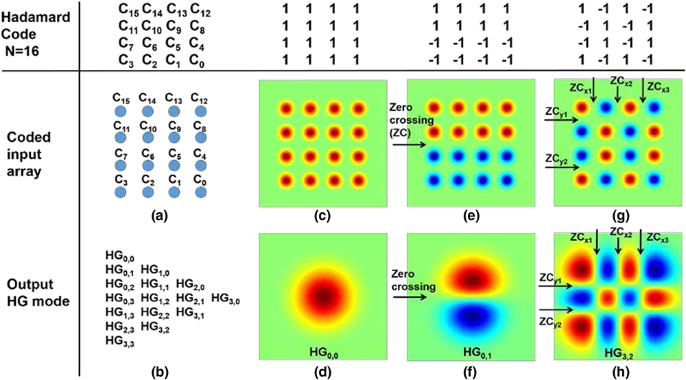
    Fig. 1. Hadamard-coded MPLC-based NMS mux for 16 HG modes. (a) Input array; (b) the HG mode set that can be generated using this NMS mux; (c) the input array coded to produce (d) the desired output HG0,0 mode; (e) the input array coded to produce (f) the desired output HG0,1 mode; (g) the input array coded to produce (h) the desired output HG3,2 mode. The locations of the zero crossings, where the adjacent spots change from negative to positive or vice versa, are identical for the input array and output modes, and they are marked by arrows. This similarity allows for a reduced number of phase plates.
    (a) Calculated phase patterns for the seven phase masks used in the MPLC-based NMS mux supporting 256 HG modes; (b)–(d) normalized intensity of the HG0,0, HG12,9 modes and all 256 HG modes at each phase mask.
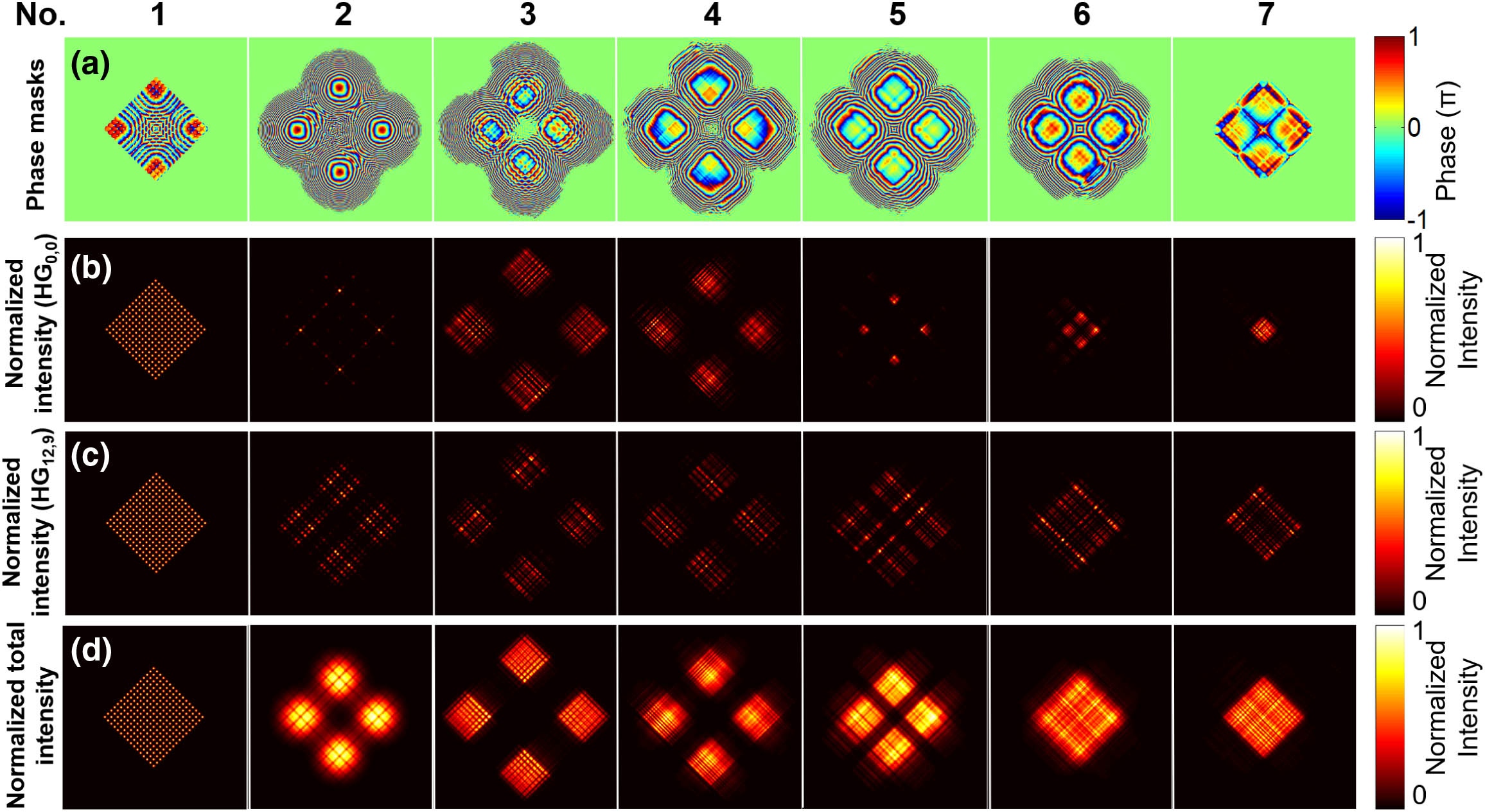
    Fig. 2. (a) Calculated phase patterns for the seven phase masks used in the MPLC-based NMS mux supporting 256 HG modes; (b)–(d) normalized intensity of the HG0,0, HG12,9 modes and all 256 HG modes at each phase mask.
    Normalized field of some input (left column) and corresponding output (right column) modes generated by the MPLC-based NMS mux in comparison to the target mode (middle column).
    Fig. 3. Normalized field of some input (left column) and corresponding output (right column) modes generated by the MPLC-based NMS mux in comparison to the target mode (middle column).
    (a) Transfer matrix, (b) loss, and (c) modal crosstalk of the MPLC-based NMS mux supporting 256 HG modes.
    Fig. 4. (a) Transfer matrix, (b) loss, and (c) modal crosstalk of the MPLC-based NMS mux supporting 256 HG modes.
    (a) Insertion loss and (b) mode-dependent loss as functions of wavelength of the MPLC-based NMS mux supporting 256 HG modes.
    Fig. 5. (a) Insertion loss and (b) mode-dependent loss as functions of wavelength of the MPLC-based NMS mux supporting 256 HG modes.
    Comparison of (a)–(c) amplitude-and-phase control with (d)–(f) phase-only control by SPGD for coherent power combination with a NMS mux supporting 16 inputs. (a), (d) Output intensity before control; (b), (e) output intensity after control; (c), (f) the phase and amplitude of inputs before (blue) and after (red) control.
    Fig. 6. Comparison of (a)–(c) amplitude-and-phase control with (d)–(f) phase-only control by SPGD for coherent power combination with a NMS mux supporting 16 inputs. (a), (d) Output intensity before control; (b), (e) output intensity after control; (c), (f) the phase and amplitude of inputs before (blue) and after (red) control.
    Comparison between amplitude-and-phase control and phase-only control. (a) The average power of output beam in defined aperture and its error bar, (b) average fundamental mode power in the output beam and its error bar, and (c) average fidelity of the output beam and its error bar over 2000 samples as functions of adjustment times in the control process. Histogram of fundamental mode power in the output beam for 2000 samples for (d) amplitude-and-phase control and (e) phase-only control.
    Fig. 7. Comparison between amplitude-and-phase control and phase-only control. (a) The average power of output beam in defined aperture and its error bar, (b) average fundamental mode power in the output beam and its error bar, and (c) average fidelity of the output beam and its error bar over 2000 samples as functions of adjustment times in the control process. Histogram of fundamental mode power in the output beam for 2000 samples for (d) amplitude-and-phase control and (e) phase-only control.
    Comparison between the optimized Fourier and randomly permutated Fourier coding schemes for an MPLC-based NMS mux for 16 inputs. (a) Coded phase of input array by the Hadamard coding (left), the optimized Fourier coding (middle), and a randomly permutated Fourier coding (right); matrix composed of the absolute values of the real part of the correlation coefficients between the Hadamard code set and (b) the optimized Fourier code set and (c) the randomly permutated Fourier code set; (d) MDL versus IL and (e) averaged total mode crosstalk versus IL of the 16-input NMS muxes using optimized Fourier coding (red star) and 1000 randomly permutated Fourier coding (blue circles).
    Fig. 8. Comparison between the optimized Fourier and randomly permutated Fourier coding schemes for an MPLC-based NMS mux for 16 inputs. (a) Coded phase of input array by the Hadamard coding (left), the optimized Fourier coding (middle), and a randomly permutated Fourier coding (right); matrix composed of the absolute values of the real part of the correlation coefficients between the Hadamard code set and (b) the optimized Fourier code set and (c) the randomly permutated Fourier code set; (d) MDL versus IL and (e) averaged total mode crosstalk versus IL of the 16-input NMS muxes using optimized Fourier coding (red star) and 1000 randomly permutated Fourier coding (blue circles).
    Comparison between the Fourier and Hadamard coding schemes for an MPLC-based NMS mux for 16 inputs in terms of (a) insertion loss, (b) mode-dependent loss, and (c) averaged total mode crosstalk with different numbers of phase masks.
    Fig. 9. Comparison between the Fourier and Hadamard coding schemes for an MPLC-based NMS mux for 16 inputs in terms of (a) insertion loss, (b) mode-dependent loss, and (c) averaged total mode crosstalk with different numbers of phase masks.
    Comparison between the Fourier and Hadamard coding schemes for an MPLC-based NMS mux with seven phase masks for different number of inputs in terms of (a) insertion loss, (b) mode-dependent loss, and (c) averaged total mode crosstalk.
    Fig. 10. Comparison between the Fourier and Hadamard coding schemes for an MPLC-based NMS mux with seven phase masks for different number of inputs in terms of (a) insertion loss, (b) mode-dependent loss, and (c) averaged total mode crosstalk.
    Comparison of the synthesized and ideal LG modes and their corresponding interferogram resulting from interfering with a fundamental Gaussian mode with a positive wavefront curvature. The 16 LG modes belong to different mode groups with mode group numbers ranging from 0 to 15. The numbers in the figure are the squared magnitude of the coupling coefficients between the synthesized and corresponding ideal LG modes.
    Fig. 11. Comparison of the synthesized and ideal LG modes and their corresponding interferogram resulting from interfering with a fundamental Gaussian mode with a positive wavefront curvature. The 16 LG modes belong to different mode groups with mode group numbers ranging from 0 to 15. The numbers in the figure are the squared magnitude of the coupling coefficients between the synthesized and corresponding ideal LG modes.
    He Wen, Yuanhang Zhang, Rachel Sampson, Nicolas K. Fontaine, Ning Wang, Shengli Fan, Guifang Li. Scalable non-mode selective Hermite–Gaussian mode multiplexer based on multi-plane light conversion[J]. Photonics Research, 2021, 9(2): 88
    Download Citation