
Xue Yang, Chengjuan Yang, Hao Tong, Huimin Qi, Yao Yao, Zhen Yang. Theoretical Analysis and Experimental Research on Tubular Electrode‑Coupled Laser and Electrochemical Hybrid Machining[J]. Chinese Journal of Lasers, 2024, 51(16): 1602402
- Chinese Journal of Lasers
- Vol. 51, Issue 16, 1602402 (2024)
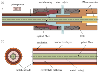
Fig. 1. Tubular electrode structure schematic diagrams. (a) Schematic diagram of fiber device and electrode device assembly; (b) schematic diagram of electrode device structure
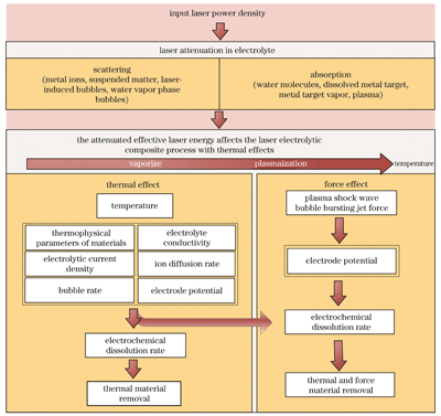
Fig. 2. Logic diagram of laser action on complex energy field
Fig. 3. Schematic diagram of laser and electrolytic pulses
Fig. 4. Schematic diagram of laser and electrochemical hybrid machining mechanism
Fig. 5. Schematic diagram of all domains and boundaries of the tubular electrode-coupled laser and electrochemical hybrid model
Fig. 6. Simulation results of tubular electrode-coupled laser and electrochemical hybrid machining. (a)‒(c) Flow field distributions at different time; (d)‒(f) pressure distributions at different time; (g)‒(i) electric filed distributions at different time; (j)‒(l) temperature distributions at different time
Fig. 7. Cross-sectional profiles. (a) Cross-section near the cathode; (b) cross-section near the anode
Fig. 8. Variations of workpiece surface temperature, electrolyte velocity, electrolyte current density, and Z-direction material removal with machining depth and processing time. (a)(b) Variation of workpiece surface temperature; (c)(d) variation of electrolyte velocity; (e)(f) variation of electrolyte current density; (g)(h) variation of with Z-direction material removal
Fig. 9. Three-dimensional morphology of blind hole cross-section. (a) Three-dimensional morphology of blind hole cross-section in electrochemical machining; (b) three-dimension morphology of blind hole cross-section in laser and electrochemical hybrid machining
Fig. 10. Morphologiy of small holes with high aspect ratio and local magnified images of the small holes edge, where the first row shows the small holes entrance, the second row shows small holes cross-section, and the third row shows the small holes exit
Fig. 11. Side wall morphology of small holes with high aspect ratio. (a) 20 mm through-hole; (b) 50 mm through-hole
|
Table 1. Simulation parameters
|
Table 2. Experimental parameters
|
Table 3. Experimental results

Set citation alerts for the article
Please enter your email address
© Copyright 2018-2021 | Chinese Laser Press. All Rights Reserved 沪ICP备15018463号-20