
Zhuang Peng, Shen Fahua, Wang Bangxin, Xie Chenbo, Shao Jiadi, Qiu Chengqun, Liu Dong, Wang Yingjian. Rayleigh-Mie Wind Lidar Based on Fabry-Perot Interferometer[J]. Chinese Journal of Lasers, 2020, 47(12): 1210001
- Chinese Journal of Lasers
- Vol. 47, Issue 12, 1210001 (2020)
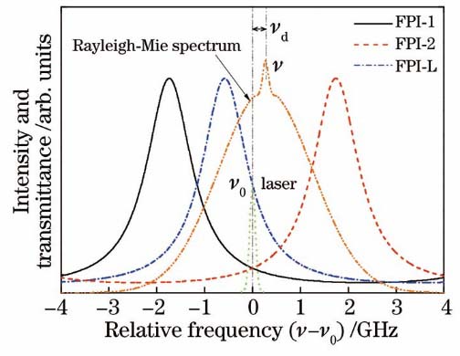
Fig. 1. Schematic of Doppler frequency measurement principle based on triple FPI
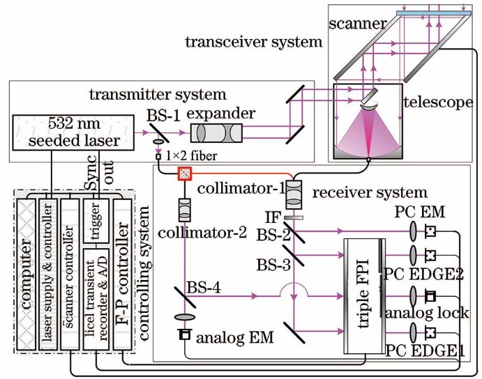
Fig. 2. Schematic of Rayleigh-Mie Doppler lidar system based on triple FPI
Fig. 3. Photos of verification system for Doppler lidar based on triple FPI
Fig. 4. PMT output pulse signal collected by high-speed A/D acquisition card
Fig. 5. Measured original transmittance data and the corresponding fitting curve when scanning the FPI cavity length
Fig. 6. FPI transmittance curves when emitted laser/Mie and Rayleigh scattering light are incident
Fig. 7. Total wind speed measurement sensitivities when Mie or Rayleigh scattering signals are incident on FPI-1 and FPI-2
Fig. 8. Five consecutive groups of radial wind speeds in the same direction. (a) Measuring profile; (b) measuring mean and variance
Fig. 9. Radial wind speed and error in East, South, West, and North with zenith angle of 27°. (a) Radial wind speed; (b) radial wind speed error
Fig. 10. Comparison results of Doppler lidar verification system and radiosonde on the afternoon of May 12,2020. (a) Horizontal wind speed; (b) horizontal wind direction
Fig. 11. Comparison results of Doppler lidar verification system and radiosonde on the night of May 18, 2020. (a) Horizontal wind speed; (b)horizontal wind direction
Fig. 12. Horizontal wind field difference measured by two detection devices on the night of May 18, 2020. (a) Horizontal wind speed difference; (b) horizontal wind direction difference
| |||||||||||||||||||||||||||||||||||||||||||||||||||||||||||||||||||||||||||||||||||
Table 1. Design parameters of verification system for Doppler lidar based on triple FPI

Set citation alerts for the article
Please enter your email address
© Copyright 2018-2021 | Chinese Laser Press. All Rights Reserved 沪ICP备15018463号-20