• Laser & Optoelectronics Progress
  • Vol. 58, Issue 22, 2208001 (2021)
Faqiang Zhang1、*, Bin Feng2, and Hongshun Li3
Author Affiliations
  • 1Department of Optoelectronic Engineering, Xi'an Technological University, Xi'an, Shaanxi 710032, China
  • 2Key Laboratory of Information Fusion Technology of Ministry of Education, School of Automation, Northwestern Polytechnical University, Xi'an, Shaanxi 710072, China
  • 3Unit 31697 of PLA, Dalian, Shenyang 116103, China
  • show less
    DOI: 10.3788/LOP202158.2208001 Cite this Article Set citation alerts
    Faqiang Zhang, Bin Feng, Hongshun Li. Research on Athermalization Design of Infrared Optical System Based on Wavefront Coding[J]. Laser & Optoelectronics Progress, 2021, 58(22): 2208001 Copy Citation Text show less
    Optical path structure of optical system. (a) Overall structure; (b) rays at focal plane
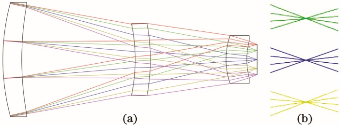
    Fig. 1. Optical path structure of optical system. (a) Overall structure; (b) rays at focal plane
    MTF curves of ordinary infrared optical systems at different temperatures. (a) +20 ℃; (b) -40 ℃; (c) +60 ℃
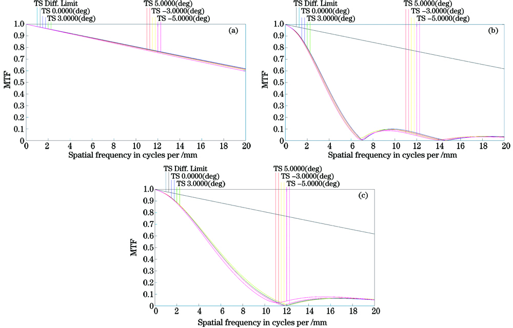
    Fig. 2. MTF curves of ordinary infrared optical systems at different temperatures. (a) +20 ℃; (b) -40 ℃; (c) +60 ℃
    Data processing diagram
    Fig. 3. Data processing diagram
    Optical path structure of wavefront coding infrared optical system. (a) Overall structure; (b) rays at focal plane
    Fig. 4. Optical path structure of wavefront coding infrared optical system. (a) Overall structure; (b) rays at focal plane
    MTF curves of wavefront coding infrared optical systems at different temperatures. (a) +20 ℃; (b) -40 ℃; (c) +60 ℃
    Fig. 5. MTF curves of wavefront coding infrared optical systems at different temperatures. (a) +20 ℃; (b) -40 ℃; (c) +60 ℃
    PSF of ordinary infrared optical system and wavefront coding infrared optical system. (a) +20 ℃; (b) -40 ℃; (c) +60 ℃
    Fig. 6. PSF of ordinary infrared optical system and wavefront coding infrared optical system. (a) +20 ℃; (b) -40 ℃; (c) +60 ℃
    Imaging results of ordinary infrared optical system and wavefront coding infrared optical system. (a) Imaging diagram of ordinary system; (b) intermediate diagram of coding system; (c) restoration diagram of coding system
    Fig. 7. Imaging results of ordinary infrared optical system and wavefront coding infrared optical system. (a) Imaging diagram of ordinary system; (b) intermediate diagram of coding system; (c) restoration diagram of coding system
    Operating waveband /μmFocal length /mmFoV /(°)FTemperature /℃Nyquist frequency /(lp·mm-1)
    8--1245101.5-40-+6020
    Table 1. Indicator of optical system
    Surface No.TypeRadius /mmThickness /mmGlass
    STOStandard58.0715.000Ge
    2Standard81.34730.000
    3Standard-46.5754.000ZnSe
    4Standard-53.30920.000
    5Standard19.1385.500Ge
    6Standard19.0912.732
    IMAStandardInfinity
    Table 2. Structural parameters of optical system
    Parameter12(STO)34
    TypeExtended polynomialStandardStandardStandard
    Radius /mm58.07181.347-46.575-53.30919.13819.091
    Thickness /mm3.05.04.05.5
    GlassZnSeGeZnSeGe
    Semi-diameter15.2915.199.656.50
    Table 3. Structural parameters of wavefront coding infrared optical system
    Faqiang Zhang, Bin Feng, Hongshun Li. Research on Athermalization Design of Infrared Optical System Based on Wavefront Coding[J]. Laser & Optoelectronics Progress, 2021, 58(22): 2208001
    Download Citation