• Chinese Optics Letters
  • Vol. 21, Issue 1, 010003 (2023)
Wanxia Huang*, Yabo Zhang, Yuan Pei, Maosheng Wang, Fenghua Shi, and Kuanguo Li
Author Affiliations
  • Anhui Key Laboratory of Optoelectric Materials Science and Technology, School of Physics and Electronic Information, Anhui Normal University, Wuhu 241002, China
  • show less
    DOI: 10.3788/COL202321.010003 Cite this Article Set citation alerts
    Wanxia Huang, Yabo Zhang, Yuan Pei, Maosheng Wang, Fenghua Shi, Kuanguo Li. Effects of propagation phase on the coupling of plasmonic optical modes[J]. Chinese Optics Letters, 2023, 21(1): 010003 Copy Citation Text show less

    Abstract

    The temporal coupled-mode theory (TCMT) has made significant progress in recent years, and is widely applied in explaining a variety of optical phenomena. In this paper, the optical characteristics of the metasurface composed of nano-bars and nano-rings are simulated. The simulation results are well explained by TCMT under the coupled basis vector. However, when the structural asymmetry is large, the fitting of results shows that the total radiation loss is not conservative, in contradiction to the requirement of traditional TCMT. We solved this inconsistency by introducing the propagation phase into the near-field coupling term of TCMT. The studies show that, unlike the local mode near the exceptional point which corresponds to the radiation loss of the bright mode, the global mode near the diabolic point is closely related to the propagation phase. Furthermore, the structure near the diabolic point shows characteristic cross-coupling with the change of period. This study proposes a new theoretical framework for comprehending the interaction of light and matter and offers some guiding implications for the application of TCMT to a variety of related domains.

    1. Introduction

    Since the introduction of the temporal coupled-mode theory (TCMT) into plasmonic optics by Fan[1,2], vigorous developments of it have been witnessed. One of TCMT’s development paths is to simplify the incident light source (normally incident light) and detection (same polarization) but increase the number of modes and ports[2-4], e.g. one-mode one-port TCMT[5], one-mode two-port TCMT, two-mode one-port TCMT, two-mode two-port TCMT[6,7]. TCMT has been used to explain a variety of novel phenomena, including Fano resonance[8], plasmon-induced transparency (PIT)[9], exceptional point (EP)[10-14], and bound-state in the continuum[15,16]. These phenomena have been widely used in coherent perfect absorbers[17], unidirectional light propagation devices[10,18], asymmetric mode switching[19], sensor[20-23], and improved Sagnac effect[24]. Another development path is to keep the mode simple, while consider complicated source and detection (port) like oblique incident light sources[25,26] and detection with different polarizations (polarization conversion)[27]. In recent years, TCMT has been further generalized[28-34]. For example, in 2021 Alu’s research group used TCMT to explain the thermal metasurface of the combined local and nonlocal light-matter interaction[25]. In 2022, Fan’s research group used it to explain the optical force spectrum of resonant structure well[32].

    Particularly, the TCMT has been generalized to describe the cross-coupling terms of the near-field, which can be real[6], virtual[35,36], complex[37], or chiral[38]. The coupling can occur either between two bright modes[31], or between the bright mode and dark mode[6]. As revealed by TCMT, especially the two-mode two-port one, the total radiation and absorption losses are usually conserved irrespective to the change of structural asymmetry degree. In this paper, we studied the optical properties of the metasurfaces composed of a nano-bar and a nano-ring in a unit cell, where the total radiation loss of the system is found to be not conserved with varied asymmetry. There exist two degenerate points in the system. The mode corresponding to one degenerate point shows obvious localization, while the modes near the other degenerate point show obvious nonlocality. With the change of period, cross-coupling between the two modes is clearly shown, which is well explained by the generalized TCMT. This research provides a theoretical scheme for the new phenomenon of mode coupling and has certain guiding significance in the design of micro- and nano-photonics devices.

    2. Structural Design and Simulation

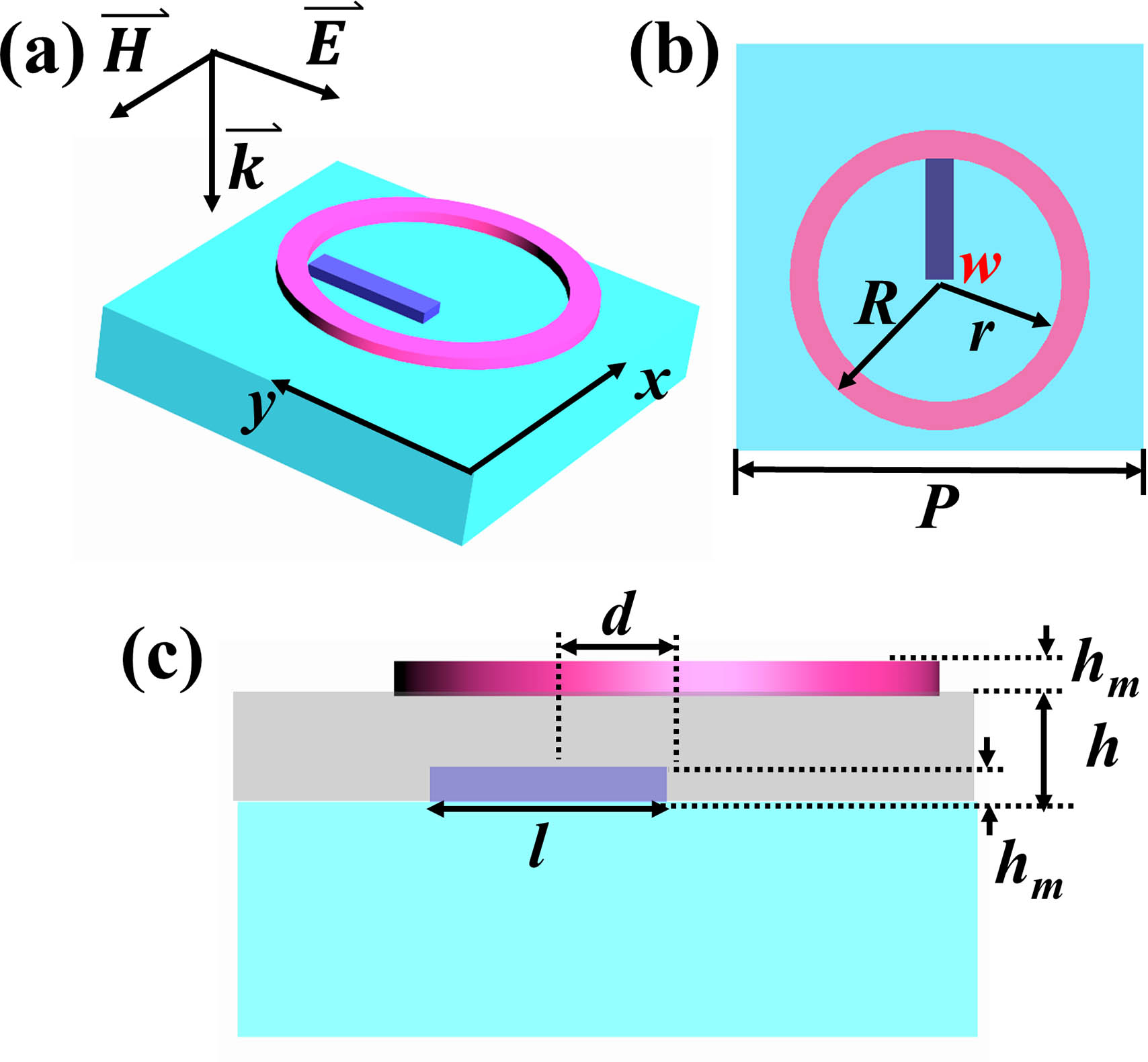
    A unit cell of the metasurface is composed of a gold nano-ring and a gold nano-bar, as shown in Fig. 1. The bar with a thickness of hm=30nm is inserted into the silica film with a thickness of h=90nm, and the thickness of the ring is hm=30nm. Without losing generality, the period P of the lattice is chosen to be 1000 nm. The length and width of the bar are l=320nm and w=70nm, respectively. The outer and inner radii of the ring are R=370nm and r=300nm, respectively. The asymmetry degree d is defined as the lateral displacement of the bottom bar along the y-axis. In order to study the optical properties of metasurfaces, finite-difference time-domain (FDTD) simulations are performed. In the simulation, the refractive indices of the glass substrate and the intermediate layer are all set to n=1.5, and that for the background is 1. The dielectric constant of gold follows the Drude model ε=1ωp2/(ω2+iωγ), where the frequencies of plasmonic resonances and damping are ωp=1.374×10¹⁶rad/s and γ=1.224×10¹⁴rad/s.

    Schematic diagram of the unit cell with the corresponding structural parameters. (a) The perspective view, (b) the top view, and (c) the side view.

    Figure 1.Schematic diagram of the unit cell with the corresponding structural parameters. (a) The perspective view, (b) the top view, and (c) the side view.

    3. Optical Characterization

    It was shown previously[39] that the PIT of this metasurface is caused by the coherent superposition of the electric dipole of the bar and the electric quadrupole of the ring, where the electric dipole acts as the bright mode and the electric quadrupole as the dark mode. The coupling between the two modes leads to the abnormal phenomenon of merging-splitting-separation-proximity-merging, i.e. the metasurfaces with varied d present two frequency degeneracy points. One is EP, which refers to degeneracies of non-Hermitian systems with coalescent eigenstates and is commonly seen in systems with gain and loss such as parity-time-symmetric systems[11]. The other one is the diabolic point (DP)[40], which is the accidental degeneracy of energy levels in parameter space. What are the different optical properties near these two degenerate points? What causes the degeneracy point?

    To answer the above questions, we use the FDTD approach to simulate spectra of metasurfaces with varied d. Figure 2 shows the simulated zeroth-order transmission (T), reflection (R), and absorption (A) spectra. The absorbance A is calculated according to A=1TR.

    Simulated (a) zeroth-order transmittance spectra, (b) reflection spectra, and (c) absorption spectra as a function of asymmetric degree d. (d)–(g) Simulated Re(Hz) patterns of the nanostructure corresponding to the absorption peak A, peak B, peak C, and peak D, respectively. (d) Simulated Re(Hz) patterns of the nanostructure with d = 60 nm at frequency fA = 180.4 THz. (e), (f) Simulated Re(Hz) patterns of the nanostructure with d = 180 nm at frequency fB = 189.1 THz and fC = 167.2 THz, respectively. (g) Simulated Re(Hz) patterns of the nanostructure with d = 360 nm at frequency fD = 173.7 THz.

    Figure 2.Simulated (a) zeroth-order transmittance spectra, (b) reflection spectra, and (c) absorption spectra as a function of asymmetric degree d. (d)–(g) Simulated Re(Hz) patterns of the nanostructure corresponding to the absorption peak A, peak B, peak C, and peak D, respectively. (d) Simulated Re(Hz) patterns of the nanostructure with d = 60 nm at frequency fA = 180.4 THz. (e), (f) Simulated Re(Hz) patterns of the nanostructure with d = 180 nm at frequency fB = 189.1 THz and fC = 167.2 THz, respectively. (g) Simulated Re(Hz) patterns of the nanostructure with d = 360 nm at frequency fD = 173.7 THz.

    It can be seen from Fig. 2 that with the increased d, the transmission dip shows the “merging-splitting-separation-proximity-merging” and obvious PIT. In Fig. 2(c), A represents the absorption peak (fA=180.4THz) of the metasurface with d=60nm, whose z-component of the magnetic field in the unit cell on the x=0nm plane is shown in Fig. 2(d). The magnetic field is located around the rod, implying a local mode. B and C represent the two absorption peaks (fB=189.1THz and fC=167.2THz) of the metasurface when d=180nm, with the z-component distribution of the magnetic field shown in Figs. 2(e) and 2(f). The magnetic field of mode B spans the whole cell, and the exchange changes of field maximum and field minimum are shown along the y-direction. It is similar to the field distribution of surface plasmon polariton (SPP)[41], therefore a global distribution. The magnetic field of mode C is also mainly localized near the bar, i.e., a local mode. D represents the absorption peak (fD=173.7THz) (DP) of the metasurface with d=360nm. The field distribution of the magnetic field, as plotted in Fig. 2(g), also shows a global field distribution similar to SPP. Why does the variation in d change the properties of the mode? This is mainly because the distance between the bar and the ring becomes farther with d=360nm. Once the electric dipole of the bar is excited and the dipolar field propagates and reaches the ring, the electric quadrupole of the ring is excited. Consequently, the field diffuses into the whole unit cell, showing the global characteristics. For d=180nm, the long-wavelength C mode is the local mode and the short wavelength B mode is the global mode.

    It can be seen from the above simulation that with changing d, the structure has two degenerate points. Are the optical properties of the structure near the two degenerate points the same? In order to answer this question, we first simulate the metasurfaces with asymmetry of d=0, 180, and 420 nm. The transmission, reflection, and absorption dispersion diagrams with the incident angle of plane wave varying from 0° to 20° are shown in Fig. 3. It can be seen from the figure that the mode with d=0nm is a local mode, and the resonance position does not shift significantly with the increase of incident angle. Two modes appear in the dispersion diagram with asymmetry d=180nm, among which the long-wavelength one does not change obviously with the change of incident angle (local mode) and the short-wavelength one shows obvious redshift (global mode). At last, the two modes gradually merge into one single mode, which is particularly obvious in the absorption spectra. Moreover, with the increase of angle, the absorption increases significantly. In the dispersion diagram of d=420nm, one mode is split into two modes. As the incident angle increases, the long-wavelength mode redshifts and the short-wavelength mode blueshifts, which show two obvious global modes. These are consistent with the conclusions given by the field distribution.

    Simulated dispersion of the nanostructure with d = 0 nm (a)–(c), d = 180 nm (d)–(f), and d = 420 nm (g)–(i).

    Figure 3.Simulated dispersion of the nanostructure with d = 0 nm (a)–(c), d = 180 nm (d)–(f), and d = 420 nm (g)–(i).

    In order to further study the differences between the two frequency degeneracy points, we also simulated the periodic spectra of metasurfaces with d=60nm and d=355nm (other structural parameters are the same as above), as shown in Fig. 4. For d=60nm, with the increase of the period, the quality factors of the two modes become larger and redshifts are observed. According to the Babinet complementarity principle[42], SPP mode exists at a shorter wavelength, which is directly proportional to the change of period P; therefore, the short-wavelength mode is squeezed by the SPP at the shorter wavelength, resulting in a larger quality factor and redshift. The long-wavelength mode has a weak redshift under extrusion, and disappears due to the competition between two modes. For d=355nm, when P changes in steps of 20 nm from 920 nm to 1160 nm, the two modes first split, then merges into one mode, and then split again. To clearly see the evolution trend, we also plotted the transmission and reflection curves with P, as shown in Figs. 5(a) and 5(b). In the figure, we can see two modes appear splitting, merging, and then splitting with the increase of P. To explore whether this coupling is cross-coupling or anti cross-coupling, the field distributions of four modes with asymmetry d=355nm and period P=1160nm (or 920 nm) at wavelength λE=1.72μm and λF=1.79μm (or λG=1.63μm and λH=1.73μm) are simulated. Figures 5(c) and 5(d) show the field distribution of the asymmetric electric quadrupole in mode E, and the field in the lower half of the ring is relatively strong. Mode F is also the field of the electric quadrupole, but it is mainly concentrated in the upper half ring. Figures 5(e) and 5(f) show the field distribution of modes G and H, also corresponding to the asymmetric electric quadrupole, but with the field concentration opposite to those of the modes E and F. That is, with the change of period, mode E evolves into mode H and mode F evolves into mode G, and the two modes appear cross-coupling. The reason is that DP is the degeneracy point between modes due to the complex and subtle relationship between the period and the size of metasurfaces.

    Simulated (a) [or (d)] zeroth-order transmittance spectra, (b) [or (e)] reflection spectra, and (c) [or (f)] absorption spectra of the nanostructures with d = 60 nm (or d = 355 nm) as a function of P.

    Figure 4.Simulated (a) [or (d)] zeroth-order transmittance spectra, (b) [or (e)] reflection spectra, and (c) [or (f)] absorption spectra of the nanostructures with d = 60 nm (or d = 355 nm) as a function of P.

    Simulated (a) zeroth-order transmittance spectra and (b) reflection spectra of the nanostructures with d = 355 nm as a function of P. (c)–(f) Simulated Re(Hz) patterns of the nanostructure corresponding to the reflection peak E, peak F, peak G, and peak H, respectively. (c), (d) [or (e), (f)] Simulated Re(Hz) patterns of the nanostructure with P = 1160 nm (or P = 920 nm) at wavelength λE = 1.72 µm and λF = 1.79 µm (or λG = 1.63 µm and λH = 1.73 µm), respectively.

    Figure 5.Simulated (a) zeroth-order transmittance spectra and (b) reflection spectra of the nanostructures with d = 355 nm as a function of P. (c)–(f) Simulated Re(Hz) patterns of the nanostructure corresponding to the reflection peak E, peak F, peak G, and peak H, respectively. (c), (d) [or (e), (f)] Simulated Re(Hz) patterns of the nanostructure with P = 1160 nm (or P = 920 nm) at wavelength λE = 1.72 µm and λF = 1.79  µm (or λG = 1.63 µm and λH = 1.73 µm), respectively.

    4. Theoretical Explanation

    The results show that the mode of the structures near EP related to the radiation loss of the bright mode is almost nondispersive. With the increase of P, the mode has a weak redshift, and the quality factor increases due to the extrusion caused by the redshifts of other modes. The DP due to the adjustment of structural parameters has obvious redshifts with the change of angle. With the increase of P, the phenomenon of splitting-merging-splitting occurs, and cross-coupling appears. The mode E becomes the mode H and the mode F becomes the mode G. According to Ref. [6], these phenomena can be explained by TCMT. The dipole of the bar acts as the bright mode (p) and the quadrupole of the ring acts as the dark mode (q). With the symmetry breaking of the structures, the coherent superposition of the two modes leads to the asymmetric line shape of the spectra. To further study the physical mechanism behind it, we choose the two-mode two-port TCMT. The Hamiltonian equation without coupling between two modes can be written as H^0|Ψp=2πfp|Ψp,H^0|Ψq=2πfq|Ψq,where |Ψp and |Ψq are eigenstates of the dipole and quadrupole modes for the symmetric nanostructure without coupling. fp and fq are their corresponding frequency. Consider our plasmonic resonator as a two-mode two-port system. And we define Sj+ and Sj (j=1,2) are the complex amplitude of the incoming and outgoing waves at the jth port. The amplitudes of the dipole and quadrupole modes in our nanostructure are represented by ap and aq, respectively. The dynamic equations for the amplitude of the resonance mode can be written as 12πddt(apaq)=i[(fp+κppκpqκqpfq+κqq)i(γp00γq)](apaq)(γp000)(apaq)+(kp1kp200)(S1+S2+),(S1S2)=(S110S120S210S220)(S1+S2+)+(d1p0d2p0)(apaq),where κpp and κqq denote the on-site corrections by the perturbation and κpq=κqp describes the near-field coupling between two original modes, again contributed by the perturbation. γβ (or γβ) is the radiation (or absorption) loss rate for the βth mode. kβj or djβ(j=1,2) is the coupling constant between the βth mode and the incoming or outgoing wave at the jth port. Sjl0(j,l=1,2) is the S-parameter matrix element of the background system. The coupling constant kβj or djβ and the radiation loss rate γβ are dependent on each other by energy conservation and time-reversal symmetry consideration. According to principles of optics[43], under normal incidence or grazing incidence, the half-wave loss will occur when light is reflected from light sparse to light dense medium. Let medium 2 be glass and medium 1 be air. The S-parameter matrix elements of the background system are S120=S210=2nn+1,S220=S110=n1n+1.

    We diagonalize the near-field term to obtain a unitary matrix and then carry out a unitary transformation for Eqs. (4) and (5). At first, the eigenfrequencies are obtained: f˜=f¯Δf˜.

    Here, we have defined f¯=(fp+κpp+fq+κqq)/2, Δf˜=(Δf)2+κpq2 and Δf=(fq+κqqfpκpp)/2 as the frequency average and difference between two modes; the subscripts “+” and “” correspond to the “dressed” dark and bright modes, respectively. We can obtain the eigenvector of the “dressed” dark mode and the “dressed” bright mode, and the transformation matrix as follows: M=(ΔfΔf˜(ΔfΔf˜)2+κpq2Δf+Δf˜(Δf+Δf˜)2+κpq2κpq(ΔfΔf˜)2+κpq2κpq(Δf+Δf˜)2+κpq2).

    Through unitary transformations on both sides of Eqs. (4) and (5), we obtain the dynamical equation of coupled representation as follows: 12πddt(a˜+a˜)=i(f˜+00f˜)(a˜+a˜)+(γ˜++γ˜+X˜X˜γ˜+γ˜)(a˜+a˜)+(k˜+1k˜+2k˜1k˜2)(S10+S20+).

    The output wave equation of coupled representation is(S10S20)=(S110S120S210S220)(S10+S20+)+(d˜1+d˜1d˜2+d˜2+)(a˜+a˜).

    The expressions of physical quantities in coupled representation are obtained: X˜=κpqγp/(2Δf˜),γ˜=γp(Δf˜+Δf)/2Δf˜,γ˜+=γp(Δf˜Δf)/2Δf˜,γ˜=γp+γq2(γqγp)Δf2Δf˜,γ˜+=γp+γq2+(γqγp)Δf2Δf˜.

    According to Eqs. (12) to (15), we obtain two conserved quantities: γ˜++γ˜=γp,γ˜++γ˜=γp+γq.

    Equations (16) and (17) show the total radiation loss and the total absorption loss are both conserved quantities during the whole evolution of the system. At the same time, Eqs. (7), (12), and (13) can inversely solve the near-field coupling coefficient under the uncoupled basis vector. κpq=f˜+f˜2γp(γp+γ˜+γ˜)(γpγ˜++γ˜),κqq=[f˜++f˜fpfq+f˜+f˜γp(γ˜γ˜+)]/2,κpp=[f˜++f˜fpfqf˜+f˜γp(γ˜γ˜+)]/2.

    The complex amplitude of transmission under the coupling basis vector can be obtained by t=2nn+12nn+1(γ˜W˜+γ˜+W˜+2γ˜γ˜+W˜W˜+)/(1γ˜γ˜+W˜W˜+),where W˜=[i(ff˜)+γ˜+γ˜]. Based on Eq. (21), the simulation results are fitted. The red circle represents the simulation results and the blue solid curve for the fitting ones, as shown in Fig. 6. The results show that the theory is in good agreement with the simulation. Figure 7 is the variation curve of fitting parameters with d. Figure 7(a) is the variation of the resonance frequency of two dressed modes with d, showing the phenomenon of “merging-splitting-separation-proximity-merging”. Figure 7(b) shows that the radiation loss of the two dressed modes changes with d. We can see the radiation loss of the dressed bright mode first decreases rapidly from the maximum and then decreases slowly, and that of the dressed dark mode increases from 0 and then decreases slowly, showing a phenomenon different from the common increase. Figure 7(c) is the curve of the absorption loss of the two dressed modes with d. It can be seen from the figure that the absorption of the two modes is almost unchanged. Figure 7(d) shows the sum frequency f˜t of the two dressed modes varies with d. It can be seen from the figure that f˜t decreases slowly before d<360nm, decreases suddenly at 360 nm, and then decreases slowly. Figure 7(e) shows the total radiation losses γ˜t with d. It is obvious from the figure that when d<200nm, γ˜t is almost conserved, about 10.3 THz. When d>200nm, γ˜t decreases linearly, and finally to the minimum of 3.7 THz, as shown in the shadow in Fig. 7(e). That is, when d>200nm, the total radiation loss is not conserved, which is inconsistent with the conservation of the total radiation loss when a near-field coupling coefficient is a real number. Figure 7(f) shows the total absorption loss γ˜t with d. It can be seen from the figure that γ˜t remains almost constant, which is consistent with the conservation of the total absorption loss when a near-field coupling coefficient is a real number.

    CMT modelling of the bright-dark coupled resonators. FDTD-simulated (red circles) and CMT-fitted (blue solid curves) transmission spectra for samples with different d values of (a) 0 nm, (b) 40 nm, (c) 140 nm, (d) 260 nm, (e) 300 nm, and (f) 380 nm.

    Figure 6.CMT modelling of the bright-dark coupled resonators. FDTD-simulated (red circles) and CMT-fitted (blue solid curves) transmission spectra for samples with different d values of (a) 0 nm, (b) 40 nm, (c) 140 nm, (d) 260 nm, (e) 300 nm, and (f) 380 nm.

    Retrieved CMT parameters as functions of d.

    Figure 7.Retrieved CMT parameters as functions of d.

    Why is the total radiation loss not conserved when d>200nm? How to explain it? When d>200nm, the bar and the ring are far away. The dipole of the bar is excited and propagates a certain distance to the ring. The quadrupole of the ring is excited by near-field coupling. Because the ring is far from the bar, there is a propagation phase in the near-field cross-coupling coefficient. The on-site term of near-field coupling indicates that the field of the bar propagates to the ring, and then the quadrupole of the ring is excited. The quadrupole field of the ring has a certain perturbation to the dipole field of the bar. Therefore, the propagation phase corresponding to this item is larger and it is reasonable to introduce the propagation phase into the near-field coupling coefficient. The master equation of dynamics under the uncoupling basis vector is 12πddt(apaq)=i[(fp+κppeiακpqeiβκpqeiβfq+κqqeiα)i(γp00γq)](apaq)(γp000)(apaq)+(kp1kp2kq1kq2)(S10+S20+)=i[(fp+κppcosακpqcosβκpqcosβfq+κqqcosα)i(γp00γq)](apaq)(γp+κppsinακpqsinβκpqsinβκqqsinα)(apaq)+(kp1kp2kq1kq2)(S10+S20+),where (fp+κppcosακpqcosβκpqcosβfq+κqqcosα) is the near-field coupling matrix, (γp+κppsinακpqsinβκpqsinβκqqsinα) is the radiation loss matrix, and (γp00γq) is the absorption loss matrix. For simplicity, we set κppcosα=κpp, κqqcosα=κqq, and κpqcosβ=κpq. Because the coupling coefficient between the incident port and two modes is not zero, both modes are bright modes. Similarly, the coupling coefficient between two modes and the exit port is also not zero. The eigenvalues can be obtained by diagonalizing the near-field coupling term f˜=f¯Δf˜.

    Here, we have defined f¯=(fp+κpp+fq+κqq)/2, Δf˜=(Δf)2+κpq2 and Δf=(fq+κqqfpκpp)/2 as the frequency average and difference between two modes, the subscript “+” corresponds to the dressed dark mode, and the subscript “” corresponds to the dressed bright mode. We substitute Eq. (23) into eigenvalue equations, and we can obtain the eigenvectors of the dressed bright mode and the dressed dark mode, and then obtain the transformation matrix as follows: M˜=(Δf+Δf˜2κpqΔf+Δf˜2κpq11).

    Through unitary transformations, the expressions of physical quantities in coupled representation are obtained: (γ˜X˜X˜γ˜+)M1(γp+κppsinακpqsinβκpqsinβκqqsinα)M=(B11B12B21B22),where B11=Δf(γp+κppsinακqqsinα)+Δf˜(γp+κppsinα2κpqsinβ+κqqsinα)2Δf˜,B12=κpqcosβ(γpκppsinα+κqqsinα)2Δf˜,B21=κpqcosβ(γpκppsinα+κqqsinα)Δf˜2Δfsinβcosβ,B22=Δf(γpκppsinα+κqqsinα)+Δf˜(γp+κppsinα+2κpqsinβ+κqqsinα)2Δf˜.

    In order to meet the requirements of energy conservation and time inversion symmetry in the coupled TCMT, here B12 must be equal to B21, then 2Δfsinβcosβ=0.

    Discuss: When sinβ=0, we obtain expressions of physical quantities in coupled representation: X˜=κpq(γp+κppsinακqqsinα)/(2Δf˜),γ˜=Δf(γp+κppsinακqqsinα)+Δf˜(γp+κppsinα+κqqsinα)2Δf˜,γ˜+=Δf(γpκppsinα+κqqsinα)+Δf˜(γp+κppsinα+κqqsinα)2Δf˜.When α=0, Eqs. (32) and (33) degenerate into Eqs. (12) and (13).When Δf=0, then X˜=γpκppsinα+κqqsinα2,γ˜=γp+κppsinα2κpqsinβ+κqqsinα2,γ˜+=γp+κppsinα+2κpqsinβ+κqqsinα2.

    Generally speaking, it is difficult to ensure Δf=0 during the whole evolution process, so here sinβ=0 is selected. The absorption losses under the coupling basis vector are γ˜+=(γpγq)Δf2Δf˜+γp+γq2,γ˜=γp+γq2(γpγq)Δf2Δf˜.

    Based on Eqs. (32), (33) and (37), (38), we obtain γ˜++γ˜=γp+κppsinα+κqqsinα,γ˜++γ˜=γp+γq.

    Equation (40) shows the total absorption loss is a conserved quantity during the whole evolution of the system. However, Eq. (39) shows the total radiation loss is not a conserved quantity. Combining Eqs. (23) and (32), (33), we obtain tanα=γ˜++γ˜γpf˜+f˜+fpfq.

    When fq=fp, further derivation can be obtained: κpp=12[γ˜++γ˜γpsinαγpcosα(γpcosα)24sinαcosα(γ˜γ˜+)(f˜+f˜)2sinαcosα],κqq=12[γ˜++γ˜γpsinα+γpcosα(γpcosα)24sinαcosα(γ˜γ˜+)(f˜+f˜)2sinαcosα],κpq=12{(f˜f˜+)2[γpcosα(γpcosα)24sinαcosα(γ˜γ˜+)(f˜f˜+)2sinα]2}0.5.

    When α=0, Eqs. (42)–(44) degenerate to Eqs. (18)–(20). Therefore, our theory is self-consistent.

    In order to verify the correctness of our hypothesis, based on Eqs. (18)–(20) [Eqs. (42)–(44)], we plot the near-field coupling coefficient of metasurfaces with d180nm (or d180nm), as shown in Fig. 8, where fp=fq=179.2THz, γp=10.3THz, γp=3.6THz, and γq=3.5THz. Figures 8(a)8(c) show the near-field coupling coefficients of metasurfaces with d180nm. As can be seen from the figure, κpq increases linearly from 0 to 10.67 THz, κpp decreases almost linearly from 0 to 4.4THz, and κqq slowly increases from 0 to 1.7 THz. Figures 8(d)8(f) show the near-field coupling coefficient κpq, the real part of κpp, and the real part of κqq for d180nm, respectively. It can be seen from the figure that the near-field coupling coefficient κpq with d180nm decreases almost linearly from 10.66 THz to 0 with d=360nm. When d360nm, κpq remains 0. The real part of κpp decreases linearly from 4.4THz to 8.8THz, and here has small fluctuations around 7THz. The real part of κqq increases slowly from 1.8 THz to 3.5 THz, and then decreases to 0 with d=340nm. When d=360nm, κqq changes suddenly to 6.9THz, and then slowly decreases to 8.8THz with the increase of d. At d=180nm, the difference between the two methods is very small, which also shows that the generalized theory is self-consistent.

    Retrieved (a), (c), (e) conventional and (b), (d), (f) generalized CMT parameters as functions of d.

    Figure 8.Retrieved (a), (c), (e) conventional and (b), (d), (f) generalized CMT parameters as functions of d.

    Figure 9(a) shows the propagation phase α variation with d. As can be seen from the figure, when d<360nm, α increases linearly from 0 to 0.77. When d=360nm, α changes suddenly from 0.77 to 0.46, then slowly to 0.415. Figure 9(b) shows the imaginary part of cκ=κppκqq with d. It can be seen from the figure that Imcκ when 240nm<d<360nm is not 0. Because the existence of the propagation phase makes the near-field coupling term more complex. The existence of the propagation phase not only changes the resonance frequency of dressed mode, but also changes the total radiation loss of dressed mode. Theoretical studies show that DP is related to the propagation phase, which is related to the period and the size of nanostructures. Therefore, the generalized TCMT well explains the simulation phenomenon.

    Based on Eqs. (41)–(43), retrieved α (a) and Imcκ (b) as functions of d.

    Figure 9.Based on Eqs. (41)–(43), retrieved α (a) and Imcκ (b) as functions of d.

    5. Conclusion

    In recent years, TCMT has made a great breakthrough, successfully explained various optical phenomena, and has a wide range of application prospects. In this paper, the optical properties of metasurfaces with the unit cell composed of nano-bar and nano-ring are numerically simulated. The TCMT under the coupled basis vector well explains the numerical simulation results. However, when the asymmetry degree is large, the total radiation loss is not conserved, which is contrary to the traditional TCMT requirement. The generalized TCMT by introducing the propagation phase into the near-field coupling term, solves this contradiction well. The results show that, unlike the local mode near EP, the global mode near DP is related to the propagation phase and shows the phenomenon of cross-coupling with the change of period. This study provides a new theoretical scheme for understanding the interaction between light and matter and has certain guiding significance for popularizing it in various related fields.

    References

    [1] S. Fan, W. Suh, J. D. Joannopoulos. Temporal coupled-mode theory for the Fano resonance in optical resonators. J. Opt. Soc. Am. A, 20, 569(2003).

    [2] W. Suh, W. Zheng, S. Fan. Temporal coupled-mode theory and the presence of non-orthogonal modes in lossless multimode cavities. IEEE J. Quantum Electron., 40, 1511(2004).

    [3] K. Ding, G. Ma, M. Xiao, Z. Zhang, C. T. Chan. Emergence, coalescence, and topological properties of multiple exceptional points and their experimental realization. Phys. Rev. X, 6, 021007(2016).

    [4] B. Yang, T. Liu, H. Guo, S. Xiao, L. Zhou. High-performance meta-devices based on multilayer meta-atoms: interplay between the number of layers and phase coverage. Sci. Bull., 64, 823(2019).

    [5] C. Qu, S. Ma, J. Hao, M. Qiu, X. Li, S. Xiao, Z. Miao, N. Dai, Q. He, S. Sun, L. Zhou. Tailor the functionalities of metasurfaces based on a complete phase diagram. Phys. Rev. Lett., 115, 235503(2015).

    [6] W. Huang, J. Lin, M. Qiu, T. Liu, Q. He, S. Xiao, L. Zhou. A complete phase diagram for dark-bright coupled plasmonic systems: applicability of Fano’s formula. Nanophotonics, 9, 3251(2020).

    [7] C. Hsu, B. G. Delacy, S. G. Johnson, J. D. Joannopoulos, M. Soljačić. Theoretical criteria for scattering dark states in nanostructured particles. Nano Lett., 14, 2783(2014).

    [8] S. Hayashi, D. V. Nesterenko, Z. Sekkat. Fano resonance and plasmon-induced transparency in waveguide-coupled surface plasmon resonance sensors. Appl. Phys. Express, 8, 022201(2017).

    [9] S. Xia, X. Zhai, L. Wang, S. Wen. Plasmonically induced transparency in in-plane isotropic and anisotropic 2D materials. Opt. Express, 28, 7980(2020).

    [10] X. Yin, X. Zhang. Unidirectional light propagation at exceptional points. Nat. Mater., 12, 175(2013).

    [11] C. Wang, W. R. Sweeney, A. D. Stone, L. Yang. Coherent perfect absorption at an exceptional point. Science, 373, 1261(2021).

    [12] H. Chen, T. Liu, H. Luan, R. Liu, X. Wang, X. Zhu, Y. Li, Z. Gu, S. Liang, H. Gao, L. Ge, S. Zhang, J. Zhu, R. Ma. Revealing the missing dimension at an exceptional point. Nat. Phys., 16, 571(2020).

    [13] Q. Song, M. Odeh, J. Zúñiga-Pérez, B. Kanté, P. Genevet. Plasmonic topological metasurface by encircling an exceptional point. Science, 373, 1133(2022).

    [14] M. A. Miri, A. Alù. Exceptional points in optics and photonics. Science, 363, 42(2019).

    [15] C. W. Hsu, B. Zhen, J. Lee, S. Chua, S. Johnson, J. Joannopoulos, M. Soljačić. Observation of trapped light within the radiation continuum. Nature, 499, 188(2013).

    [16] B. Zhen, C. W. Hsu, L. Lu, A. Stone, M. Soljačić. Topological nature of optical bound states in the continuum. Phys. Rev. Lett., 113, 257401(2014).

    [17] J. R. Piper, S. Fan. Total absorption in a graphene monolayer in the optical regime by critical coupling with a photonic crystal guided resonance. ACS Photonics, 1, 347(2014).

    [18] X. Yin, J. Jin, M. Soljačić, C. Peng, B. Zhen. Observation of topologically enabled unidirectional guided resonances. Nature, 580, 467(2020).

    [19] J. Doppler, A. Mailybaev, J. Böhm, U. Kuhl, A. Girschik, F. Libisch, T. J. Miburn, P. Rabl, N. Moiseyev, S. Rotter. Dynamically encircling an exceptional point for asymmetric mode switching. Nature, 537, 76(2016).

    [20] S. Romano, G. Zito, S. Yépez, S. Cabrini, E. Penzo, G. Coppola, I. Rendina, V. Mocella. Tuning the exponential sensitivity of a bound-state-in-continuum optical sensor. Opt. Express, 27, 18776(2019).

    [21] J. Park, A. Ndao, W. Cai, L. Hsu, A. Kodigala, T. Lepetit, Y. Lo, B. Kanté. Symmetry-breaking-induced plasmonic exceptional points and nanoscale sensing. Nat. Phys., 16, 462(2020).

    [22] W. Chen, S. Özdemir, G. Zhao, J. Wiersig, L. Yang. Exceptional points enhance sensing in an optical microcavity. Nature, 548, 192(2017).

    [23] H. Hodaei, A. Hassan, S. Wittek, H. Garcia-Gracia, R. Ei-Ganainy, D. N. Christodoulides, M. Khajavikhan. Enhanced sensitivity at higher-order exceptional points. Nature, 548, 187(2017).

    [24] Y. H. Lai, Y. K. Lu, M. G. Suh, Z. Yuan, K. Vahala. Observation of the exceptional-point-enhanced Sagnac effect. Nature, 576, 65(2019).

    [25] A. C. Overvig, S. A. Mann, A. Alù. Thermal metasurfaces: complete emission control by combining local and nonlocal light-matter interactions. Phys. Rev. X, 11, 021050(2021).

    [26] Y. Jia, M. Qiu, H. Cui, S. Fan, Z. Ruan. Theory of half-space light absorption enhancement for leaky mode resonant nanowires. Nano Lett., 15, 5513(2015).

    [27] Y. Guo, M. Xiao, S. Fan. Topologically protected complete polarization conversion. Phys. Rev. Lett., 119, 167401(2017).

    [28] S. Assawaworrarit, X. Yu, S. Fan. Robust wireless power transfer using a nonlinear parity-time-symmetric circuit. Nature, 546, 387(2017).

    [29] D. Miller, L. Zhu, S. Fan. Universal modal radiation laws for all thermal emitters. Proc. Natl. Acad. Sci., 114, 4336(2017).

    [30] Z. Zhao, C. Guo, S. Fan. Connection of temporal coupled-mode-theory formalisms for a resonant optical system and its time-reversal conjugate. Phys. Rev. A, 99, 033839(2019).

    [31] J. Lin, M. Qiu, X. Zhang, H. Guo, Q. Cai, S. Xiao, Q. He, L. Zhou. Tailoring the lineshapes of coupled plasmonic systems based on a theory derived from first principles. Light Sci. Appl., 9, 158(2020).

    [32] L. Fan, Z. Zhao, R. W. Jin, M. Orenstein, S. Fan. Lineshape study of optical force spectra on resonant structures. Opt. Express, 30, 6142(2022).

    [33] Q. Li, X. Cai, T. Liu, M. Jia, Q. Wu, H. Zhou, H. Liu, Q. Wang, X. Ling, C. Chen, F. Ding, Q. He, Y. Zhang, S. Xiao, L. Zhou. Gate-tuned graphene meta-devices for dynamically controlling terahertz wavefronts. Nanophotonics, 11, 2085(2022).

    [34] P. A. Shafirin, V. V. Zubyuk, A. A. Fedyanin, M. R. Shcherbakov. Nonlinear response of Q-boosting metasurfaces beyond the time-bandwidth limit. Nanophotonics, 11, 4053(2022).

    [35] S. H. Mousavi, A. B. Khanikaev, J. Allen, M. Allen, G. Shvets. Gyromagnetically induced transparency of metasurfaces. Phys. Rev. Lett., 112, 117402(2014).

    [36] Y. Choi, C. Hahn, J. W. Yoon, S. H. Song. Observation of an anti-PT-symmetric exceptional point and energy-difference conserving dynamics in electrical circuit resonators. Nat. Commun., 9, 2182(2018).

    [37] R. D. Kekatpure, E. S. Barnard, W. Cai, M. L. Brongersma. Phase-coupled plasmon-induced transparency. Phys. Rev. Lett., 104, 243902(2010).

    [38] S. Soleymani, Q. Zhong, M. Mokim, S. Rotter, R. EI-Ganainy, K. Özdemir. Chiral and degenerate perfect absorption on exceptional surfaces. Nat. Commun., 13, 599(2022).

    [39] W. Huang, C. Zhu, M. Wang, K. Li, J. Shi, F. Zhang. Plasmon-induced transparency in ring-bar meta-atom. AIP Adv., 8, 035202(2018).

    [40] J. Yang, C. Qian, X. Xie, K. Peng, S. Wu, F. Song, S. Sun, J. Dang, Y. Yu, S. Shi, J. He, M. J. Steer, I. G. Thayne, B. Li, F. Bo, Y. Xiao, Z. Zuo, K. Jin, C. Gu, X. Xu. Diabolical points in coupled active cavities with quantum emitters. Light Sci. Appl., 9, 6(2020).

    [41] W. Huang, X. Zhang, Q. Wang, M. Wang, C. Li, K. Li, X. Yang, J. Shi. Controllability of surface plasmon polaritions far field radiation using metasurface. Photonics Res., 7, 728(2019).

    [42] M. Horák, V. Křápek, M. Hrtoň, A. Konečná, F. Ligmajer, M. Stöger-Pollach, T. Šamořil, A. Paták, Z. Édes, O. Metelka, J. Babocký, T. Šikola. Limits of Babinet’s principle for solid and hollow plasmonic antennas. Sci. Rep., 9, 4004(2019).

    [43] M. Born, E. Wolf. Principles of Optics(1999).

    Wanxia Huang, Yabo Zhang, Yuan Pei, Maosheng Wang, Fenghua Shi, Kuanguo Li. Effects of propagation phase on the coupling of plasmonic optical modes[J]. Chinese Optics Letters, 2023, 21(1): 010003
    Download Citation