• Advanced Photonics
  • Vol. 3, Issue 2, 024003 (2021)
Abdul Rahim1、2、*, Artur Hermans1、2, Benjamin Wohlfeil3, Despoina Petousi3, Bart Kuyken1、2, Dries Van Thourhout1、2, and Roel Baets1、2、*
Author Affiliations
  • 1Ghent University, Photonics Research Group, Department of Information Technology, Ghent, Belgium
  • 2Ghent University, IMEC and Center for Nano- and Biophotonics, Ghent, Belgium
  • 3ADVA Optical Networking, Berlin, Germany
  • show less
    DOI: 10.1117/1.AP.3.2.024003 Cite this Article Set citation alerts
    Abdul Rahim, Artur Hermans, Benjamin Wohlfeil, Despoina Petousi, Bart Kuyken, Dries Van Thourhout, Roel Baets, "Taking silicon photonics modulators to a higher performance level: state-of-the-art and a review of new technologies," Adv. Photon. 3, 024003 (2021) Copy Citation Text show less
    (a) Baseline architecture of carrier injection, carrier depletion, and carrier accumulation plasma dispersion phase shifters. (b) Various configurations of plasma dispersion phase shifters.
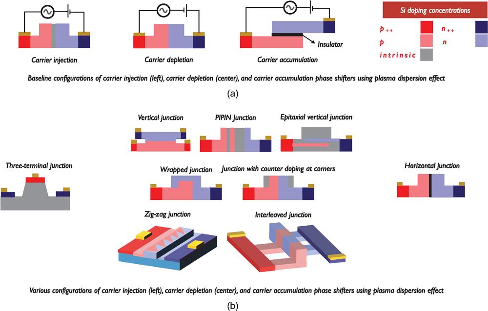
    Fig. 1. (a) Baseline architecture of carrier injection, carrier depletion, and carrier accumulation plasma dispersion phase shifters. (b) Various configurations of plasma dispersion phase shifters.
    Representative cross sections of (a) FK-based EAMs and (b) QCS effect-based EAMs in SiPh. This figure also highlights the integration route for the respective EAMs. The term monolithic refers to the integration of a material with an SOI substrate using wafer-scale epitaxial growth resulting in PICs made out of one substrate technology in mass on a wafer level.
    Fig. 2. Representative cross sections of (a) FK-based EAMs and (b) QCS effect-based EAMs in SiPh. This figure also highlights the integration route for the respective EAMs. The term monolithic refers to the integration of a material with an SOI substrate using wafer-scale epitaxial growth resulting in PICs made out of one substrate technology in mass on a wafer level.
    Representative cross sections of (a) LiNbO3, (b) BTO, (c) PZT, and (d) organics modulators in SiPh. This figure also highlights the integration route for each material. The term monolithic refers to the integration of a material with a SiPh substrate using wafer-scale epitaxial growth resulting in PICs made out of one substrate technology in mass on a wafer level.
    Fig. 3. Representative cross sections of (a) LiNbO3, (b) BTO, (c) PZT, and (d) organics modulators in SiPh. This figure also highlights the integration route for each material. The term monolithic refers to the integration of a material with a SiPh substrate using wafer-scale epitaxial growth resulting in PICs made out of one substrate technology in mass on a wafer level.
    Representative cross sections of (a) III–V on Si phase modulator and (b) III–V on Si EAM.
    Fig. 4. Representative cross sections of (a) III–V on Si phase modulator and (b) III–V on Si EAM.
    Representative cross sections of (a) single-layer graphene phase/amplitude modulator and (b) double-layer graphene amplitude/phase modulator in SiPh.
    Fig. 5. Representative cross sections of (a) single-layer graphene phase/amplitude modulator and (b) double-layer graphene amplitude/phase modulator in SiPh.
    The landscape of high-speed modulators in silicon photonics
    ModulationOperating principlePlatformReported optical implementationReported driver implementation
    PhasePlasma dispersion effect by carrierSiliconMZI, michelson, resonators (ring, disk, ph. crystal, Fabry–Perot), slow-light structure, Bragg reflectorsLumped, traveling wave (TW), segmented
    (a) Injection
    (b) Accumulation
    (c) Depletion
    Pockels effectLiNbO3 on siliconMZILumped, TW
    Organics on siliconMZI, ring resonatorLumped, TW
    BTO on siliconMZI, ring resonatorLumped, TW
    PZT on siliconMZI, ring resonatorLumped
    Interband transitions2D materials on siliconMZI, ring resonatorLumped, TW
    Carrier accumulations/carrier depletion+Franz-Keldysh effectIII-V on siliconMZI, ring resonatorLumped, TW
    AmplitudeFranz-Keldysh effectSilicon-germaniumWaveguide, MZILumped
    Quantum confined Stark effectGe-Si-Ge quantum wellsWaveguide, Fabry–Perot cavityLumped
    Electrical gating2D materials on siliconWaveguideLumped
    Quantum confined Stark effectIII-V on siliconWaveguideLumped
    Table 1. Prominent approaches for high-speed modulation in SiPh. The modulator implementations in SiPh use a variety of physical phenomenons, materials, optical architectures, and driver architectures.
    PrincipleModulation efficiency Vπ·L (V·cm)Loss (dB/cm)Lengtha of phase shifter (mm)Data rateb(Gb/s)Energy/bit (fJ/bit)
    Carrier injectionc<0.5 (0.0588)70 (287)0.1 to <0.3<40 (707)1000 for MZMs and RMs (0.1f,98)
    Carrier accumulationd<0.3 (0.1669)50 to 80 (3569)0.540 (405)>200 for MZMs, <200 (3105) for SLMsg
    Carrier depletione2 (0.529)10 to 30 (2.610)>1>40 (100122,123)200 for MZMs (32.419), <40 for RMs (0.918)
    Table 2. Typical and state-of-the-art performance matrix for the plasma dispersion high-speed phase modulators. The parentheses contain the best-reported result for a performance attribute. The matrix includes the results reported for O-band and C-band demonstrations.
    PrincipleFoM ER/ILLoss (dB)Modulator length (mm)Data ratea (Gb/s)Energy/bit (fJ/bit)
    FK effectb<2 (231)<6 (4.8133)0.050>40 (100137)<50 (1320)
    Quantum-confined Stark effectc<2 (7.9149)<6 (1.3149)<0.25<10 (7147)<100 (16148)
    Table 3. Typical and state-of-the-art performance matrix for amplitude modulation by the FK effect and QCS effect. The best-reported performance attributes are mentioned in parentheses.
    SchemeModulation efficiency Vπ·L (V·cm)Loss (dB/cm)Length of phase shifter (mm)Data rateb(Gb/s)Energy/bit (fJ/bit)
    LiNbO3 integrated with SiPhc<3 (2.2174)1 (0.98174)>1>70 (100174)>100 (170174)
    BaTiO3 integrated with SiPhd<0.5 (0.2182)>40 (6182)>1>40 (72180)<100179
    PZT integrated with SiPhe1 (1183)1 (1183)>240 (40184)-
    Organics integrated with SiPhf<0.05 (0.032190)<45 (20228)<1.5>50 (100196)<100 (0.7192)
    Table 4. Typical and state-of-the-art performance matrix for the ferroelectric and organic high-speed phase modulators in SiPh.a The parentheses contain the best-reported result for a performance attribute.
    OperationModulation efficiency Vπ·L (V·cm)Loss (dB/cm)Length of phase shifter (mm)Data ratea(Gb/s)Energy/bit (fJ/bit)
    Forward biased III–V on Si as a phase modulatord<0.1 (0.047161)<30 (19.4161)<0.5>30 (32163,b)100
    Reverse biased III–V on Si as a phase modulatord<0.2 (0.11164)(28280)<0.5200c,280100280
    OperationFoM ER/ILLoss (dB)Modulator length (mm)Data ratea (Gb/s)Energy/bit (fJ/bit)
    III–V on Si as an amplitude modulatord2 (2140)(4.9140)0.150 (50)140-
    Table 5. Typical and state-of-the-art performance matrix for the III–V on Si high-speed modulators in SiPh. The parentheses contain the best-reported result for a performance attribute.
    OperationModulation efficiency Vπ·L (V·cm)Loss (dB/cm)Length of phase shifter (mm)Data ratea(Gb/s)Energy/bit (fJ/bit)
    2D Materials on Si as phase modulatorb<0.5 (0.28201)>200 (236201)<0.5d10 (10201)1000 (600)1) for MZM; <500 for RM
    OperationFoM ER/ILLoss (dB)Modulator Length (mm)Data ratea (Gb/s)Energy/bit (fJ/bit)
    2D Materials on Si as amplitude modulatorc<3 (4.9155)<4 (0.9203)<0.15>10 (50154)100 (40202)
    Table 6. Typical and state-of-the-art performance matrix for graphene on Si high-speed modulators in SiPh. The parentheses contain the best-reported result for a performance attribute.
    Abdul Rahim, Artur Hermans, Benjamin Wohlfeil, Despoina Petousi, Bart Kuyken, Dries Van Thourhout, Roel Baets, "Taking silicon photonics modulators to a higher performance level: state-of-the-art and a review of new technologies," Adv. Photon. 3, 024003 (2021)
    Download Citation