
G. Lehmann, K. H. Spatschek. Reflection and transmission properties of a finite-length electron plasma grating[J]. Matter and Radiation at Extremes, 2022, 7(5): 054402
- Matter and Radiation at Extremes
- Vol. 7, Issue 5, 054402 (2022)
Abstract
I. INTRODUCTION
Because the damage threshold of a plasma is orders of magnitude higher than that of solid-state optics, plasma components are investigated intensively for manipulating laser light at high intensities.1–3 In recent years, plasma mirrors,4,5 wave- and q-plates,6,7 and plasma-based polarizers8–10 have shown enormous potential as high-intensity photonic devices, and active consideration is being given to plasma optical modulators,11 active plasma lenses,12–15 plasma holograms,16–19 terahertz radiation sources,20 and plasma-based beam combiners for very high fluence and energy.21 Also, plasma parametric amplification22–27 and the use of plasma mirrors for focusing are now part of the newly developing domain of plasma optics, which will eventually lead to high-intensity lasers.28
Among the proposed optical components are plasma gratings,29–31 also known as plasma photonic crystals (PPCs).32–35 A PPC can be understood as a periodic modulation of the refractive index, with a period close to the wavelength of light.36 The formation of deep electron and ion density gratings by using two counterpropagating and intersecting laser pulses began to be studied in the early 2000s,29,37 and since then many details and applications have been worked out.4,5,10,11,18,38–46 PPCs are now promising optical devices that can withstand laser intensities above the solid-state damage threshold, and many applications have been discussed.
To date, the main interest has been robust gratings that are established relatively slowly and persist on time scales longer than the inverse ion plasma frequency. However, for some problems in basic physics (e.g., frequency up-conversion of lasers and photon acceleration47–52), it may be desirable to have a rapidly created and evolving plasma grating at one’s disposal, and the main aim herein is to elucidate some features of such a rapid grating. Note that a rapid electron grating appears in the initial phase of a ponderomotive ion grating, but for the latter, the two generating counterpropagating pump laser pulses persist for sufficiently long times that ions may react. Instead, if one uses short pump pulses, then only the first electron reaction appears, and it will persist for as long as the pump pulses intersect each other. Therefore the following question arises: how can one study, for example, the reflection and transmission properties of such a volatile grating? The answer is related to nonlinear polarization transfer and control of two laser beams overlapping in a uniform nonlinear medium.53
We investigate the short-pulse interaction scenario in which a circularly polarized laser pulse interacts with a counterpropagating y-polarized laser pulse. We treat the circularly polarized wave as a superposition of two linearly polarized components that we designate as z- and y-polarized, respectively, and the interaction of the y components (parallel polarization) leads to standing density changes in the plasma. Because of the shortness of the laser beams, the plasma dynamics are dominated initially by only electrons as they respond to the ponderomotive pressure, and an electron grating can appear for a time of no more than the inverse ion plasma frequency, with the wave with a z component propagating in the grating. Note that a standing electron grating differs from the moving train of potential wells of two slightly detuned laser pulses that collide in a plasma and give rise to a short-duration burst of coherent terahertz radiation.54
Because of the limited time of the ponderomotive pressure, an electron grating is finite in both space and time. Therefore, its properties cannot be explained by (infinite) Bloch wave analysis, and instead we develop a theory based on four-wave mixing,31,55–57 which explains the transmission and reflection of the z-polarized component when interacting with the grating. The present four-wave-mixing theory differs from previous models because we do not have parallel polarization of all four waves. This allows us to simplify the otherwise complex scenario into two manageable parts, i.e., (i) the generation of a grating by the y components and (ii) propagation of the z component in a modulated plasma, and we compare the predictions of the four-wave-mixing model with the results of extensive particle-in-cell (PIC) simulations. An alternative to the present modeling is analysis with a finite transfer-matrix calculation for layered matter, and that method is outlined in the Appendix (perhaps for later use when considering more details of grating structures); however, we do not evaluate the transfer-matrix method in all its specifics because the much simpler four-wave-mixing model already gives convincing results.
The rest of this paper is organized as follows. In Sec. II, we present the considered arrangement and PIC simulations. The simulations are for counterpropagating and interacting short laser pulses of the same frequency; by short, we mean that the duration of a laser pulse is of the order of 40 fs in a plasma whose density is 5% of the critical density. We analyze the generated electron grating itself and its transition and reflection properties for electromagnetic waves. In Sec. III, we discuss the understanding provided by the PIC simulations, and we develop a four-wave-mixing theory to interpret the numerical results. We conclude in Sec. IV with a short summary and outlook, and in the Appendix we discuss an alternative method for analyzing finite PPCs.
II. PARTICLE-IN-CELL SIMULATION OF A FINITE ELECTRON GRATING
A. General arrangement
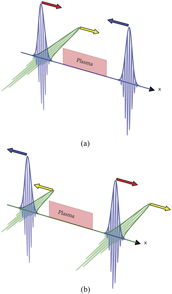
An electron grating appears when two counterpropagating laser pulses interact in a plasma, and the scenario is sketched in Fig. 1. Figure 1(a) shows the initial state. In general, the laser pulse propagating from the left can be either linearly or circularly polarized, and in the latter case we decompose it into two linearly polarized ones; the left beam propagates in the positive x direction and comprises a y-polarized component (in purple) and a z-polarized component (in green). The second laser beam (propagating from the right in the negative x direction) is always y-polarized (in purple). The y components produce the plasma grating, while the z component feels the density modulations. Figure 1(b) shows a later stage at which the original (initial) pulses have left the plasma, and we observe transmission and reflection; of particular interest here is the behavior of the z component (in green).
![]()
Figure 1.(a) Initial situation in which two counterpropagating pulses approach a plasma slab; the left one (in purple and green) is circularly polarized, while the right one (in purple) is linearly polarized. (b) Transmission and reflection after the initial pulses have traversed the plasma.
The two laser beams shown in Fig. 1(a) should be short, by which we mean that the duration of laser-pulse overlap is less than the inverse ion plasma frequency. Below, we present some typical numbers.
The vacuum laser frequency is ω0 ≈ 2.35 × 10¹⁵ s−1, leading to a period of fs. The wavelength is λ0 = 0.8 μm, and the wavenumber is k0 ≈ 8 × 104 cm−1. We measure the mean (electron) plasma density in terms of the critical density nc, with the latter being when the laser frequency equals the plasma frequency, i.e., . When n0 = 0.05nc, we obtain ωpe0 ≈ 0.528 × 10¹⁵ s−1 and fs. For a hydrogen plasma, the ion plasma frequency is ωpi ≈ 1.23 × 10¹³ s−1 and fs. We assume a typical pulse-duration FWHM (full width at half maximum of the electric field) as being 40 fs. The y components of the two laser beams may have equal intensities of order I0 = 5 × 10¹⁶ W/cm2, leading to a normalized vector potential a0 = eA0/mec of the order of .
In Sec. II C, we present PIC simulations showing the growth and lifetime of a pure electron grating.
B. Simulation technique and parameters
To simulate the interaction of the laser pulses in a one-dimensional geometry, we use the EPOCH particle-in-cell (PIC) code.58 The total length of the simulation box is 400 μm, and we use 15 000 cells (i.e., 30 cells per λ0). In the center of the simulation box sits a (pre-ionized) hydrogen plasma slab of 100 μm in length with homogeneous density n0 = 0.05nc. To the left and right of the plasma, there is 150 μm of vacuum. We simulate mobile electrons and ions (Z = 1, mi = 1836me) and use 250 pseudoparticles per species per occupied cell. We use the cold-plasma approximation, but we also performed several runs with finite electron temperature, and when varying the latter (e.g., around 100 eV) we found no significant changes.
From the left boundary of the simulation domain, we inject a circularly polarized laser pulse with electric field components Ey and Ez, and from the right boundary we inject a linearly polarized laser pulse of equal duration but with only an Ey component. The Ey components of the two pulses have equal intensity, and hereinafter mention of pulse intensity refers to that of the Ey components. The Ez component of the circularly polarized pulse has the same intensity as that of the Ey component, otherwise the pulse would be elliptically polarized; however, the intensity of the Ez component could be less than that of the Ey component, and all subsequent conclusions would still be valid. We define the pulse duration τ as the FWHM of the electric field and use a Gaussian temporal pulse shape. The pulses arrive at the center of the simulation box (and thus of the plasma slab) at the same time.
C. Electron grating
Here, we present results for the density ripples produced by interacting laser pulses, and a typical example is shown in Fig. 2. We plot the temporal evolution of electron (upper figure) and ion (lower figure) density contours vs x, with the spatial coordinate in units of λ0 and time t in femtoseconds.
![]()
Figure 2.Temporal evolutions of electron density
Between 830 and 870 fs, the y-polarized components of the two 40 fs FWHM laser pulses with equal intensity of 1017 W/cm2 overlap and drive a strong electron density modulation. During that time period, the ions are mostly quiet; their response sets in later and leads to the typical behavior of an ion grating.
Figure 3(a) shows a snapshot of the electron grating at time t = 850 fs for the same parameter values as those for Fig. 2. Clearly, the grating has a finite extent of over ∼25 wavelengths λ0. The distribution of the density spikes is inhomogeneous, reflecting the pulse shapes of the driving laser pulses. Therefore, we cannot expect exact agreement (in all details) with analytical models based on finite but more-or-less rectangular density grating distributions. Note that the grating distribution is almost independent of the polarization of the left laser pulse if the y component in the circularly polarized case has the same amplitude as that in the linearly polarized case.
![]()
Figure 3.(a) Spatial modulations of electron density (blue or light gray line) and ion density (black line) at
To demonstrate the different time scales on which electrons and ions react to the overlapping laser pulses, in Fig. 3(b) we show the electron and ion densities in the center of the grating as functions of time; this is where we observe the largest electron density modulation throughout the simulation. The electrons react almost instantaneously to the laser fields once the two driving pulses begin to overlap (t ≈ 810 fs), and the modulation of the electron density then follows closely that of the local laser intensity. After t ≈ 850 fs, the two pulses separate and the local electron density relaxes to almost its initial value. Meanwhile, the ions ( fs) have been attracted to the electron density spike and have begun their dynamics, which lead eventually to the formation of an electron–ion plasma grating. This collective grating forms on a time scale of and has been studied previously; herein, we focus on the electron grating that occurs on the time scale of .
D. Concurrent interaction of electromagnetic pulses
Here, we focus on the behavior of the Ez component when the left driving laser pulse is circularly polarized. Typical distributions of electric fields Ey and Ez are shown in Fig. 4 before (a) and after (b) interaction of the initial laser pulses.
![]()
Figure 4.Electric fields
Starting with the two pulses having equal amplitude before interacting [case (a) in Fig. 4], we recognize that after interaction [case (b) in Fig. 4] the field components Ey and Ez are being reflected and transmitted, respectively. For the y component, it is difficult to distinguish between reflection and transmission because we have two counterpropagating Ez fields already at the beginning. However, the two Ez pulses in the lower part of Fig. 4 can clearly be apportioned to reflection and transmission, respectively. In the absence of Ez, the two Ey pulses labeled with (b) (upper panel of Fig. 4) would be symmetric, and their slight asymmetry for Ez ≠ 0 points to (nonlinear) interaction effects that are not considered further here.
In Sec. II E, we investigate how the transmission and reflection rates depend on the plasma and laser parameters.
E. Transmission and reflection
Transmission and reflection of the Ez field depend mainly on two parameters, i.e., (i) the FWHM pulse duration τ and (ii) the intensity of the laser pulses that drive the electron grating. From the simulations, we determine the fractions R and T of the incident pulse energy that is reflected and transmitted, respectively; for R = 1, the Ez field would be completely reflected, and for T = 1 it would be completely transmitted. We obtain these fractions by summing in the left and right vacuum regions before and after the pulse interaction, respectively. Because the duration of the transmitted and reflected components of Ez is almost identical to that of the incoming pulses, R and T can also be interpreted as the fractions of the power that are transmitted or reflected, respectively. Figure 5(a) shows how R and T depend on the pulse duration τ for three different values of the intensity I0 of the driving pulses. Note that the grating length L is proportional to the pulse duration τ.
![]()
Figure 5.(a) Transmission ratio
Two tendencies are evident. First, the transmission (resp. reflection) decreases (resp. increases) with increasing pulse duration τ. Second, there is a crossover point τcrossover after which reflection dominates transmission, and τcrossover decreases with increasing intensity I0.
III. FOUR-WAVE-MIXING MODEL AND ITS PREDICTIONS
In this section, we discuss the interaction of the Ez pulse with an electron grating by four-wave mixing. Note that the present situation differs significantly from degenerate four-wave-mixing55 because the latter occurs only for four parallel polarized waves.
A. Reflection and transmission in four-wave-mixing model
In the present case, the four waves are polarized in the y and z directions, and the four-wave scenario is shown schematically in Fig. 6. Waves 2 and 4 constitute a circularly (or elliptically) polarized laser pulse from the left, while wave 1 corresponds to a linearly (y-)polarized laser pulse from the right. Note that the analytical treatment is for waves and not pulses, given that the latter would require numerical evaluation of some integrals; nevertheless, the following simplified theory reproduces the main scaling behavior.
![]()
Figure 6.Visualization of four-wave-mixing scenario discussed herein. Waves 1 and 2 produce the grating, while wave 4 propagates therein, becoming partially transmitted and partially reflected (the latter being wave 3). Shown here is a general four-wave-mixing scenario, including wave 3 in the region
In the following, we distinguish between the y-polarized pulses 1 and 2 (also called pump waves) and the z-polarized pulse 4 that because of transmission and reflection also generates the wave-3 pulse. Via their ponderomotive forces, the two y-polarized pump waves 1 and 2 generate a density grating, and depending on the amplitudes, we are in either the collective or trapping regime.5,10,22,32,44,59,60 The initial (relative) electron density perturbation obeys the equation
The general solution of Eq. (1) is
For the following discussion, it is helpful to use
We start with A3(x) and assume interaction in the plasma between zero and L, in which case we have
Next, we make the natural assumption A3(L) = 0 and obtain
Thus, we have expressed the reflected amplitude A3(0) and the transmitted amplitude A4(L) in terms of the incident amplitude A4(0). Note that
![]()
Figure 7.(a) Plots of reflection coefficient
We recognize clearly the dependence on the length L of the system. Previous plasma-grating calculations were for infinite extent, but of course finite systems can be considered by a matrix approach without using Bloch’s theorem, and such a calculation is presented in the Appendix.
An electron grating of infinite extent would lead to a band gap for waves with the same frequency ω as that of the pump waves (with frequency ω0), and this agrees with the behavior shown in Fig. 7(b) for κL → ∞. The power reflectivity and the power transmission are defined as
The factor i in A3(0) points to a phase change of the backward-propagating Ez wave. However, because we consider only a one-dimensional configuration, we cannot draw conclusions about phase conjugation.
B. Parameter κL
Although simplified considerably, the present model should explain the scaling behavior seen in the numerical results. Specifically, the pump-amplitude dependence and the finite-length effects are contained in the dependencies on the parameter κL.
First, for fixed intensity I0 (i.e., fixed κ), the theory predicts that increases with L [Fig. 7(b)], and this is exactly what the simulations showed [Fig. 5(b)]. Second, the theory predicts that for smaller intensity I0 (i.e., smaller κ) we obtain a crossover from transmission-dominated to reflection-dominated conditions at larger L [Fig. 7(a)], and because L corresponds directly to τ, this again explains the simulation results in Fig. 5.
Most of the present PIC simulations were performed for . For example, for pulses with power intensity I0 = 5 × 10¹⁶ W/cm−2, we have and ωb ≈ 0.21ω0, which we evaluate for ω0 ≈ 2.4 × 10¹⁵ s−1. For laser pulses of 40 fs in duration, we estimate L from fs and obtain κL ≈ 1.1. For such a value, according to Fig. 7, reflection of Ez will be of the same order, which agrees remarkably well with the PIC simulations.
IV. SUMMARY AND DISCUSSION
Herein, we studied a dynamic electron grating driven by counterpropagating lasers. The fast electron response also occurs during the initial development of an ion grating, but in the case of short pump pulses it is the only significant plasma reaction. The lifetime of a pure electron grating is short (depending on the pump-pulse duration and the inverse ion plasma frequency), and the structure develops rapidly and may be of interest for studying frequency conversion. Also, a pure electron grating is of finite extent, and so infinite-length theories based on Bloch wave solutions are inappropriate for investigating the optical properties of an electron grating.
The specific scenario studied herein—i.e., the z component of a circularly polarized pulse experiencing an electron grating driven by the y components of that pulse and a second linearly polarized pulse—can be interpreted as either an ultra-fast pulse splitter (in reflection and transmission) or a mechanism for altering the polarization state of the circularly polarized laser pulse.
To investigate interaction with other waves, it is important to take due note of the finite lifetime. We overcame this difficulty by preparing a specific initial configuration: one of the pump laser pulses was linearly (y-)polarized, while the other had circular polarization, and we decomposed the latter into the y and z directions. The interaction of the y components led to the development of a steady electron grating, and the z component felt the density ripples and was partially reflected and partially transmitted. The ratio of reflection to transmission depended on several parameters, and we considered in detail the sensitivity to the pulse strength and duration. One-dimensional PIC simulations supplied data over a broad range, and the theoretical interpretation via four-wave mixing showed the dependence on κL that correctly described the numerical findings.
In some respects, the present modeling perhaps oversimplifies what is actually a complex situation. Another scheme that could be used to analyze the present configuration is outlined in the Appendix. The finite transfer-matrix method may be applied and generalized to handle different aspects such as inhomogeneity and random variations in the height and strength of the unit cells, but we leave that for future considerations (also for other types of gratings). Currently, the four-wave-mixing theory is sufficient for a rough classification of the main phenomena.
In the present work, we studied the possibility of using electron gratings as pulse splitters, but the range of possible applications seems much wider, and it seems reasonable to expect that many of the previously investigated applications of ion gratings (e.g., wave plates, polarizers, holograms) could also be realized with fast electron gratings. Further work is in progress, especially on the transition from a short electron grating to a wider (more extended) ion grating. In asymmetric situations (i.e., when gratings are produced by pulses of different lengths), density modulations and wake fields may act as seeds for effective Raman scattering. Returning to the present configuration, we reason that frequency up-conversion in a rapidly developing electron grating requires further attention, with the potential to give new insights into basic phenomena.
ACKNOWLEDGMENTS
Acknowledgment. Computational support and infrastructure were provided by the Centre for Information and Media Technology (ZIM) at the University of Düsseldorf (Germany). Development of the EPOCH PIC code used in this work was funded in part by the Engineering and Physical Sciences Research Council (UK) (Grant Nos. EP/G054950/1, EP/G056803/1, EP/G055165/1, and EP/M022463/1).
APPENDIX: REFLECTION AND TRANSMISSION BY TRANSFER-MATRIX METHOD
To investigate the properties of a finite electron grating, one may also use the transfer-matrix method for periodic structures.
Here, we split the whole grating (within the block named “plasma” in
It is straightforward to show that the transfer matrix
To determine the transmission rate, we require the element
The element
The numerical evaluation requires specification of
![]()
Figure 8.Plot of
However, a grating produced by short pump pulses will show spatial inhomogeneity, so the strict assumption of periodicity is not satisfied. In future work, we will account for the spatial inhomogeneity and randomness of gratings, in which case the present finite transfer-matrix method may be the method of choice.
The Bloch wave case (infinite grating) occurs for
References
[1] V. M.Malkin, N. J.Fisch. Manipulating ultraintense laser pulses in plasmas. Phys. Plasmas, 12, 044507(2005).
[2] R. L.Berger, L.Lancia, H.Peng, C.Riconda, S.Weber, J.-R.Marquès, F.Amiranoff. Plasma optics in the context of high intensity lasers. Matter Radiat. Extremes, 4, 065401(2019).
[3] P.Michel. Plasma photonics: Manipulating light using plasmas(2021).
[4] S.Monchocé, P.Martin, F.Réau, F.Quéré, S.Kahaly, A.Leblanc, P.D’Oliveira, P.Combis, L.Videau, D.Garzella. Optically controlled solid-density transient plasma gratings. Phys. Rev. Lett., 112, 145008(2014).
[5] K. H.Spatschek, G.Lehmann. Laser-driven plasma photonic crystals for high-power lasers. Phys. Plasmas, 24, 056701(2017).
[6] T.Chapman, J. D.Moody, C. Y.Chen, L.Divol, J. S.Ross, N.Woolsey, C.Goyon, B. B.Pollock, P.Michel, E.Tubman, D.Turnbull. High power dynamic polarization control using plasma photonics. Phys. Rev. Lett., 116, 205001(2016).
[7] N. J.Fisch, Q.Jia, K.Qu. Plasma q-plate for generation and manipulation of intense optical vortices. Phys. Rev. E, 96, 053207(2017).
[8] D. J.Stark, T.Toncian, R. D.Hazeltine, C.Bhattacharjee, S. M.Mahajan, A. V.Arefiev. Relativistic plasma polarizer: Impact of temperature anisotropy on relativistic transparency. Phys. Rev. Lett., 115, 025002(2015).
[9] D.Mariscal, L.Divol, J. D.Moody, S.Patankar, D.Turnbull, P.Michel, C.Goyon, G. E.Kemp, B. B.Pollock, J. S.Ross. Refractive index seen by a probe beam interacting with a laser-plasma system. Phys. Rev. Lett., 118, 015001(2017).
[10] G.Lehmann, K. H.Spatschek. Plasma-based polarizer and waveplate at large laser intensity. Phys. Rev. E, 97, 063201(2018).
[11] D. A.Jaroszynski, L. L.Yu, J.Zhang, Y.Zhao, M.Chen, W. B.Mori, S. M.Weng, Z. M.Sheng, L. J.Qian. Plasma optical modulators for intense lasers. Nat. Commun., 7, 11893(2016).
[12] L.Piersanti, F.Filippi, D.Pellegrini, D.Di Giovenale, A.Giribono, S.Bini, E.Brentegani, R.Pompili, G.Costa, A. R.Rossi, V.Shpakov, A.Zigler, A.Stella, M.Ferrario, E.Chiadroni, A.Mostacci, C.Vaccarezza, S.Romeo, M.Croia, M.Marongiu, F.Cardelli, M. P.Anania, G.Di Pirro, V.Martinelli, V.Lollo, M.Bellaveglia, G.Castorina, F.Bisesto, A.Biagioni, F.Villa, O.Coiro, A.Marocchino, A.Cianchi, J.Scifo. Focusing of high-brightness electron beams with active-plasma lenses. Phys. Rev. Lett., 121, 174801(2018).
[13] R.Corsini, L.Schaper, J.Osterhoff, K. N.Sjobak, A. E.Dyson, S. M.Hooker, G.Boyle, M.Meisel, W.Farabolini, E.Adli, J.-H.R?ckemann, C. A.Lindstr?m. Emittance preservation in an aberration-free active plasma lens. Phys. Rev. Lett., 121, 194801(2018).
[14] A.Kon, R.Kodama, P.Audebert, M.Nakatsutsumi, J.Fuchs, S.Buffechoux. Fast focusing of short-pulse lasers by innovative plasma optics toward extreme intensity. Opt. Lett., 35, 2314(2010).
[15] J.Osterhoff, K.Poder, A.Martinez de la Ossa, M.Zeng. Plasma lenses for relativistic laser beams in laser wakefield accelerators. Phys. Plasmas, 27, 023109(2020).
[16] I. Y.Dodin, N. J.Fisch. Storing, retrieving, and proprocess optical information by Raman backscattering in plasmas. Phys. Rev. Lett., 88, 165001(2002).
[17] N. J.Fisch, I. Y.Dodin. Dynamic volume holography and optical information processing by Raman scattering. Opt. Commun., 214, 83-98(2002).
[18] K. H.Spatschek, G.Lehmann. Plasma volume holograms for focusing and mode conversion of ultraintense laser pulses. Phys. Rev. E, 100, 033205(2019).
[19] N. M.Fasano, E.Kur, J. S.Wurtele, M. R.Edwards, V. R.Munirov, J. M.Mikhailova, N.Lemos, P.Michel, A.Singh. Holographic plasma lenses. Phys. Rev. Lett., 128, 065003(2022).
[20] G.Lehmann, K. H.Spatschek. Wakefield stimulated terahertz radiation from a plasma grating. Plasma Phys. Controlled Fusion, 64, 034001(2022).
[21] D. P.Turnbull, D. J.Strozzi, L.Divol, P. A.Michel, B. E.Blue, T.Chapman, J. D.Moody, R. K.Kirkwood, L. A.Pickworth, O. L.Landen, B. J.MacGowan, K. B.Fournier, B. M.Van Wonterghem, W. H.Dunlop, S. C.Wilks, M. D.Rosen, R. A.London. Plasma-based beam combiner for very high fluence and energy. Nat. Phys., 14, 80(2017).
[22] G.Shvets, N. J.Fisch, J.Meyer-ter-Vehn, A.Pukhov. Superradiant amplification of an ultrashort laser pulse in a plasma by a counterpropagating pump. Phys. Rev. Lett., 81, 4879(1998).
[23] V. M.Malkin, G.Shvets, N. J.Fisch. Fast compression of laser beams to highly overcritical powers. Phys. Rev. Lett., 82, 4448-4451(1999).
[24] C.Riconda, M. N.Quinn, M.Chiaramello, L.Vassura, S.Weber, J.Fuchs, T.Gangolf, A.Giribono, A.Frank, J. R.Marquès, A.Castan, A.Chatelain, L.Lancia. Signatures of the self-similar regime of strongly coupled stimulated Brillouin scattering for efficient short laser pulse amplification. Phys. Rev. Lett., 116, 075001(2016).
[25] P.-E.Masson-Laborde, W.Rozmus, Y.Horovitz, V.Chvykov, C.McGuffey, T.Matsuoka, V.Yanovsky, J.Ludwig, A. E.Hussein, A.Maksimchuk, K.Behm, K.Krushelnick. Stimulated Raman backscattering from a laser wakefield accelerator. New J. Phys., 20, 073039(2018).
[26] S.Bolanos, R. L.Berger, J.Fuchs, T.Gangolf, L.Lancia, C.Riconda, S.Weber, F.Amiranoff, M.Chiaramello, M.Blecher, J.-R.Marquès, O.Willi. Joule-level high-efficiency energy transfer to sub-picosecond laser pulses by a plasma-based amplifier. Phys. Rev. X, 9, 021008(2019).
[27] Q.Chen, Z.Wu, S.Suckewer, A.Morozov. Compression of laser pulses by near-forward Raman amplification in plasma. Phys. Plasmas, 27, 013104(2020).
[28] S.Weber, K. H.Spatschek, A.Frank, J.Fuchs, J.-R.Marquès, O.Willi, G.Lehmann, L.Lancia, L.Vassura, C.Riconda, T.Toncian, G.Mourou. Amplification of ultra-short light pulses by ion collective modes in plasmas. Eur. Phys. J.: Spec. Top., 223, 1153-1156(2014).
[29] Z.-M.Sheng, J.Zhang, D.Umstadter. Plasma density gratings induced by intersecting laser pulses in underdense plasmas. Appl. Phys. B, 77, 673(2003).
[30] C. A.Thomas, M. J.Edwards, D. E.Hinkel, S.Dixit, D. A.Callahan, S. H.Glenzer, S. W.Haan, P.Michel, B. J.MacGowan, L.Divol, J. D.Lindl, J. D.Salmonson, E. A.Williams, S.Weber, L. J.Suter. Tuning the implosion symmetry of ICF targets via controlled crossed-beam energy transfer. Phys. Rev. Lett., 102, 025004(2009).
[31] L.Divol, J. D.Moody, P.Michel, D.Turnbull. Dynamic control of the polarization of intense laser beams via optical wave mixing in plasmas. Phys. Rev. Lett., 113, 205001(2014).
[32] K. H.Spatschek, G.Lehmann. Transient plasma photonic crystal for high-power lasers. Phys. Rev. Lett., 116, 225002(2016).
[33] S.Weber, C.Riconda, J. Q.Su, H.Peng, M.Grech. Nonlinear dynamics of laser-generated ion-plasma gratings: A unified description. Phys. Rev. E, 100, 061201(2019).
[34] R. L.Luthi, C. W.Carr, K. R.Manes, S. E.Schrauth, R. J.Wallace, M. A.Norton, M. J.Shaw, A. V.Hamza, W. G.Hollingsworth, B. J.MacGowan, M. L.Spaeth, P.Michel, R. C. W.Plummer, A.Colaitis, J.-M.Di Nicola. Study of self-diffraction from laser generated plasma gratings in the nanosecond regime. Phys. Plasmas, 26, 073108(2019).
[35] H.Peng, C.-T.Zhou, C.Riconda, S.Weber, M.Grech. Dynamical aspects of plasma gratings driven by a static ponderomotive potential. Plasma Phys. Controlled Fusion, 62, 115015(2020).
[36] I. A.Ozheredov, A. P.Shkurinov, A. V.Balakin, D.Boucher, A. V.Andreev, P.Masselin, G.Mouret. Compression of femtosecond laser pulses in thin one-dimensional photonic crystals. Phys. Rev. E, 63, 016602(2000).
[37] Z.-M.Sheng, Y.Cang, Q.-J.Zhang, H.-C.Wu, J.Zhang. Controlling ultrashort intense laser pulses by plasma Bragg gratings with ultrahigh damage threshold. Laser Part. Beams, 23, 417-421(2005).
[38] S.Suntsov, D.Abdollahpour, S.Tzortzakis, D. G.Papazoglou. Femtosecond laser induced plasma diffraction gratings in air as photonic devices for high intensity laser applications. Appl. Phys. Lett., 94, 251104(2009).
[39] Y.Yin, Y. Y.Ma, H. Y.Chen, C. L.Tian, H. B.Zhuo, H.Xu, F. Q.Shao. Moving electron density gratings induced in the beat-wave field of two counterpropagating laser pulses. Phys. Plasmas, 17, 083112(2010).
[40] S.Hocquet, J.Néauport, N.Bonod. Recent progress in the development of pulse compression gratings. EPJ Web Conf., 59, 07002(2013).
[41] A.Mysyrowicz, A.Jarnac, A.Houard, M.Richardson, Y.Liu, B.Prade, M.Durand. Spatiotemporal cleaning of a femtosecond laser pulse through interaction with counterpropagating filaments in air. Phys. Rev. A, 89, 023844(2014).
[42] N. J.Fisch, Q.Jia, I.Barth, J. M.Mikhailova, M. R.Edwards. Distinguishing Raman from strongly coupled Brillouin amplification for short pulses. Phys. Plasmas, 23, 053118(2016).
[43] J.Vieira, Y.Shi, R.Bingham, B. F.Shen, R. M. G. M.Trines, R. J.Kingham. Magnetic field generation in plasma waves driven by copropagating intense twisted lasers. Phys. Rev. Lett., 121, 145002(2018).
[44] G.Lehmann, K. H.Spatschek. Plasma photonic crystal growth in the trapping regime. Phys. Plasmas, 26, 013106(2019).
[45] J. T.Morrison, E. A.Chowdhury, W. M.Roquemore, G. K.Ngirmang, K. M.George, J. R.Smith, C.Orban. Particle-in-cell simulations of density peak formation and ion heating from short pulse laser-driven ponderomotive steepening. Phys. Plasmas, 26, 123103(2019).
[46] H. H.Ma, P.Mckenna, Z. M.Sheng, Y. X.Wang, M.Chen, S. H.Yew, X. F.Li, S. M.Weng, P.Li. Growth, saturation and breaking down of laser-driven plasma density gratings. Phys. Plasmas, 27, 073105(2020).
[47] F. R.Morgenthaler. Velocity modulation of electromagnetic waves. IEEE Trans. Microwave Theory Tech., 6, 167(1958).
[48] W. B.Mori, J. M.Dawson, S. C.Wilks. Frequency up-conversion of electromagnetic radiation with use of an overdense plasma. Phys. Rev. Lett., 61, 337(1988).
[49] P. K.Shukla, J. T.Mendon?a. Time refraction and time reflection: Two basic concepts. Phys. Scr., 65, 160(2002).
[50] K.Qu, M. R.Edwards, N. J.Fisch, Q.Jia. Theory of electromagnetic wave frequency upconversion in dynamic media. Phys. Rev. E, 98, 023202(2018).
[51] D. H.Froula, J. P.Palastro, D.Turnbull, J.Bromage, J.Katz, A. L.Milder, I. A.Begishev, P.Franke, J. L.Shaw, R.Boni. Ionization waves of arbitrary velocity. Phys. Rev. Lett., 120, 225001(2018).
[52] C. T.Zhou, S. C.Ruan, H.Peng, C.Riconda, S.Weber. Frequency conversion of lasers in a dynamic plasma grating. Phys. Rev. Appl., 15, 054053(2021).
[53] M.Lazarow, P.Michel, E.Kur, J. S.Wurtele. Nonlinear polarization transfer and control of two laser beams overlapping in a uniform nonlinear medium. Opt. Express, 29, 1162(2021).
[54] D. A.Jaroszynski, M. S.Hur, Y.-K.Kim, B.Ersfeld, T.Kang, K. B.Kwon, H. S.Song. High-energy, short-duration bursts of coherent terahertz radiation from an embedded plasma dipole. Sci. Rep., 8, 145(2018).
[55] A.Yariv, D. M.Pepper. Amplified reflection, phase conjugation, and oscillation in degenerate four-wave mixing. Opt. Lett., 1, 16(1977).
[56] B. K.Sinha, G. P.Gupta. Phase conjugation in the low reflectivity regime by nearly degenerate four-wave mixing in a homogeneous plasma. Phys. Plasmas, 5, 2252(1998).
[57] L.Divol, T.Chapman, G. J.Williams, D. A.Mariscal, D.Turnbull, M. R.Edwards, C.Goyon, N.Lemos, A. M.Hansen, P.Michel. Slow and fast light in plasma using optical wave mixing. Phys. Rev. Lett., 126, 205001(2021).
[58] P.Gillies, C. P.Ridgers, A.Lawrence-Douglas, K.Bennett, H.Schmitz, M. G.Ramsay, C. S.Brady, N. J.Sircombe, T. D.Arber, A. R.Bell, R. G.Evans. Contemporary particle-in-cell approach to laser-plasma modelling. Plasma Phys. Controlled Fusion, 57, 113001(2015).
[59] R. H.Dicke. Coherence in spontaneous radiation processes. Phys. Rev., 93, 99(1954).
[60] E.Takahashi, J.Meyer-ter-Vehn, K. J.Witte, M.Dreher. Observation of superradiant amplification of ultrashort laser pulses in a plasma. Phys. Rev. Lett., 93, 095001(2004).
[61] P.Yeh. Optical Waves in Layered Media(1988).
[62] S.Satpathy, Z.Zhang. Electromagnetic wave propagation in periodic structures: Bloch wave solution of Maxwell equations. Phys. Rev. Lett., 65, 2650(1990).

Set citation alerts for the article
Please enter your email address
© Copyright 2018-2021 | Chinese Laser Press. All Rights Reserved 沪ICP备15018463号-20