
Jingyu Zhang, Jieji Ren, Fei Li, Xiaohan Pei, Mingjun Ren. Adaptive Structured Light Projection Modulation Method Based on BRDF Model[J]. Acta Optica Sinica, 2021, 41(9): 0912001
- Acta Optica Sinica
- Vol. 41, Issue 9, 0912001 (2021)
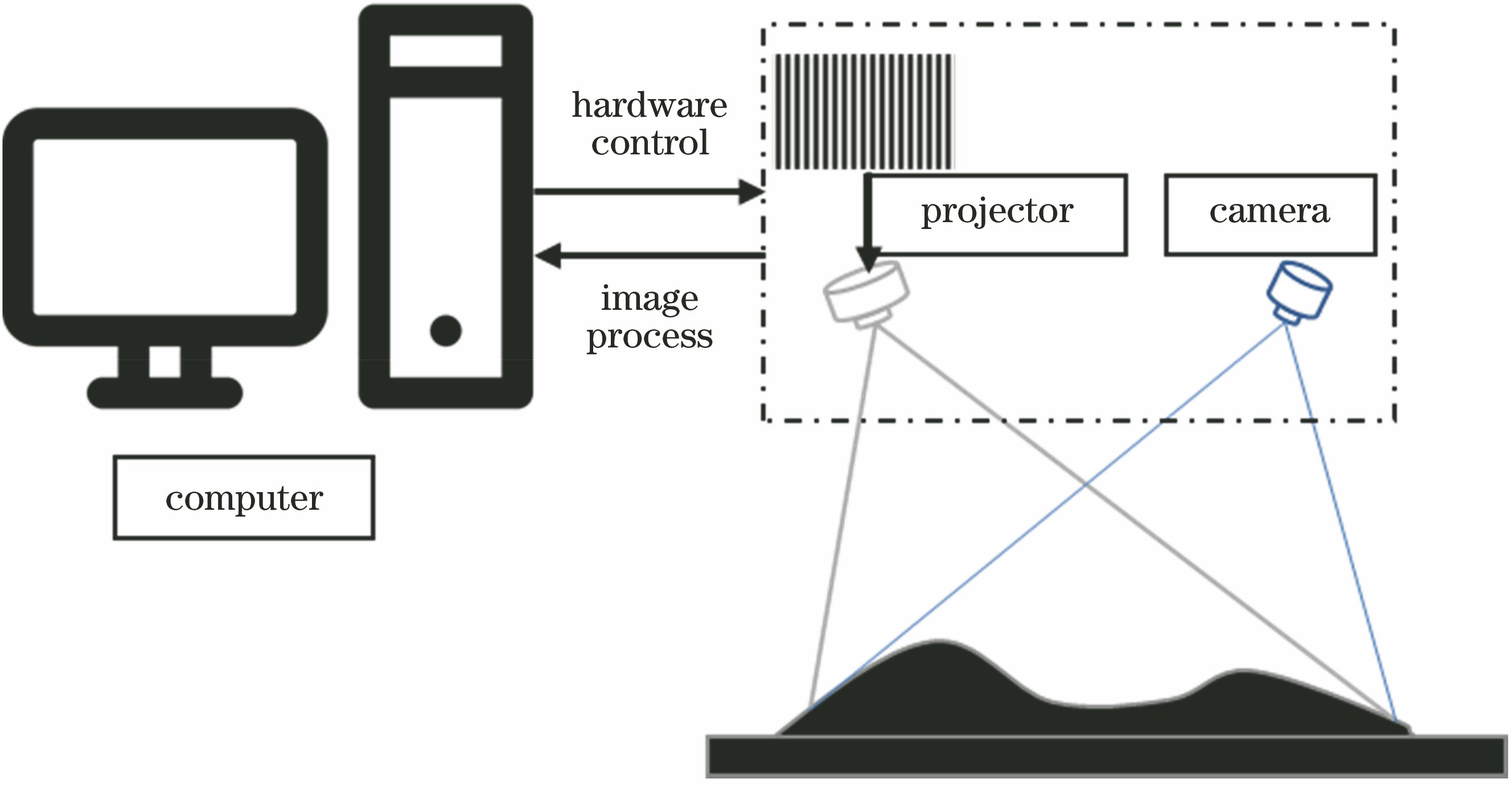
Fig. 1. Schematic of fringe projection system
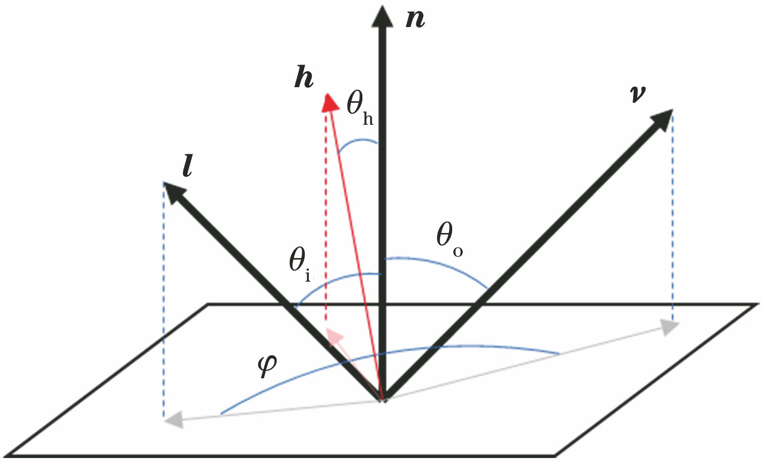
Fig. 2. Schematic of bidirectional reflection on object surface
Fig. 3. Flowchart of the system
Fig. 4. Image stereo rectification
Fig. 5. BRDF parameter distribution of plane under custom parameters
Fig. 6. BRDF distribution fitting process. (a) BRDF distribution in highlight area; (b) BRDF high-order surface fitting distribution in highlight area; (c) fitting error distribution
Fig. 7. Image matching process. (a) Original projected image; (b) original image taken by camera; (c) image in real scene; (d) one-dimensional alignment image between camera and projector after matching and correction
Fig. 8. Comparison between BRDF and real light intensity. (a) Metal surface image under real scene; (b) comparison between BRDF distribution and real light intensity distribution
Fig. 9. Experience part
Fig. 10. System experiment. (a) Original image; (b)unmodulated fringe pattern; (c) unmodulated depth diagram; (d) unmodulated point clouds; (e)modulated fringe pattern; (f) modulated depth diagram; (g) modulated point clouds
Fig. 11. Accuracy verification experiment. (a) Step point clouds; (b) Plane fitting and distance between steps
|
Table 1. Completeness analysis of pixels in depth map
|
Table 2. Calculation time of each stage of fringe projection
| |||||||||||||||||||||||||||||||||||||||||||||||||||||||||
Table 3. Accuracy verification experimental data

Set citation alerts for the article
Please enter your email address
© Copyright 2018-2021 | Chinese Laser Press. All Rights Reserved 沪ICP备15018463号-20