• Infrared and Laser Engineering
  • Vol. 49, Issue 3, 0303008 (2020)
Yongkai Yin1, Zonghua Zhang2, Xiaoli Liu3, and Xiang Peng3
Author Affiliations
  • 1School of Information Science and Engineering, Shandong University, Qingdao 266237, China
  • 2School of Mechanical Engineering, Hebei University of Technology, Tianjin 300130, China
  • 3College of Physics and Optoelectronic Engineering, Shenzhen University, Shenzhen 518060, China
  • show less
    DOI: 10.3788/IRLA202049.0303008 Cite this Article
    Yongkai Yin, Zonghua Zhang, Xiaoli Liu, Xiang Peng. Review of the system model and calibration for fringe projection profilometry[J]. Infrared and Laser Engineering, 2020, 49(3): 0303008 Copy Citation Text show less
    Typical system diagram of the fringe projection profilometry
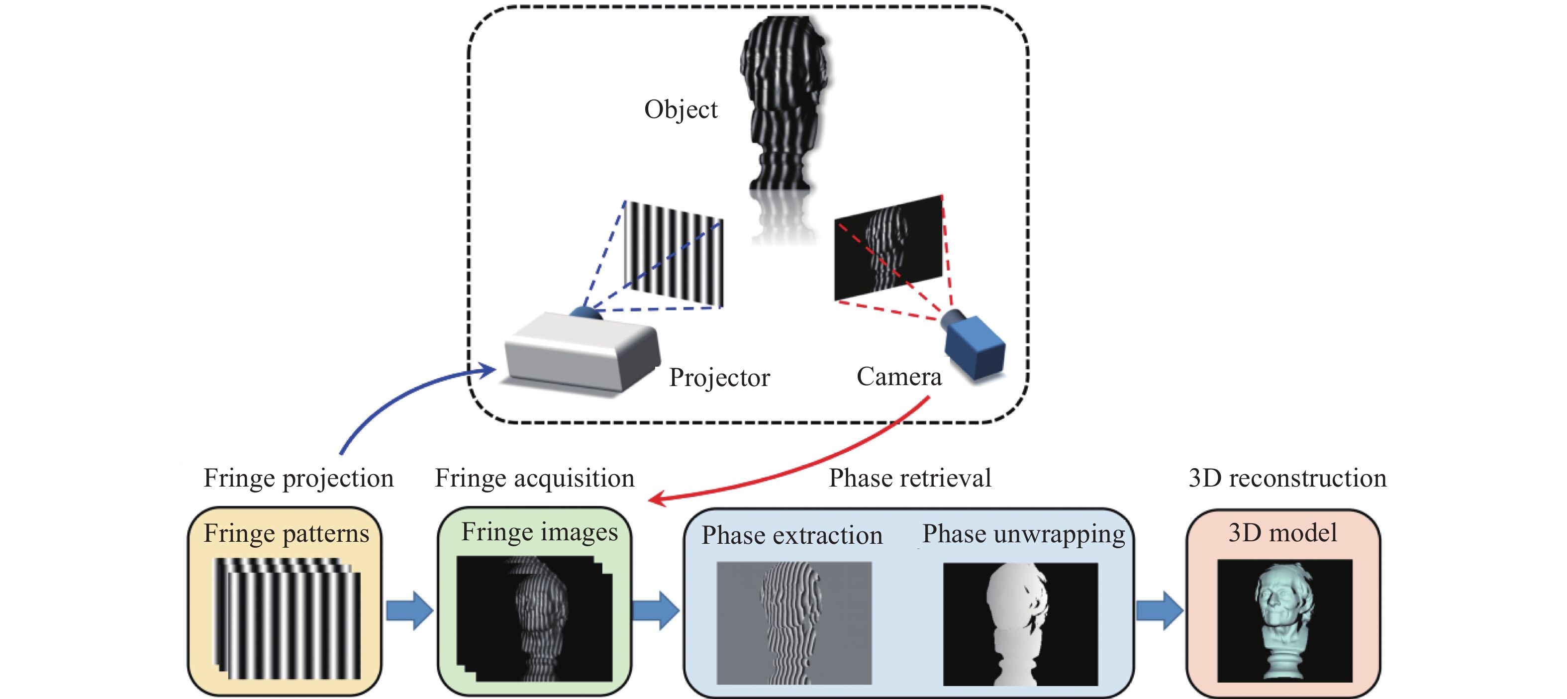
    Fig. 1. Typical system diagram of the fringe projection profilometry
    Basic elements of the fringe projection profilometry and their internal relations. Here φ denotes the phase distribution; m is the 2D image coordinate; X is the 3D space coordinate; θ is the parameter vector containing multiple parameters
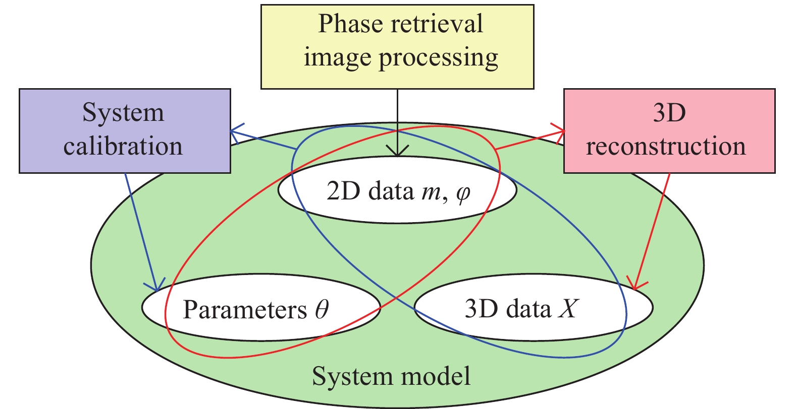
    Fig. 2. Basic elements of the fringe projection profilometry and their internal relations. Here φ denotes the phase distribution; m is the 2D image coordinate; X is the 3D space coordinate; θ is the parameter vector containing multiple parameters
    Schematic diagram of the phase-to-height conversion. (a) Reference plane only; (b) 3D imaging for the object
    Fig. 3. Schematic diagram of the phase-to-height conversion. (a) Reference plane only; (b) 3D imaging for the object
    Schematic illustration of an arbitrarily arranged FPP setup[35]
    Fig. 4. Schematic illustration of an arbitrarily arranged FPP setup[35]
    Ray tracing of one pixel in FPP[42]
    Fig. 5. Ray tracing of one pixel in FPP[42]
    Camera model
    Fig. 6. Camera model
    Determination of the homologous image coordinate in the projection pattern according to the orthogonal phase maps
    Fig. 7. Determination of the homologous image coordinate in the projection pattern according to the orthogonal phase maps
    Schematic of the binocular stereo vision model
    Fig. 8. Schematic of the binocular stereo vision model
    Translating the calibration object attached dot matrix to acquire the calibration data[47]
    Fig. 9. Translating the calibration object attached dot matrix to acquire the calibration data[47]
    Blocks gauges for system calibration[52]. (a) Top view of the calibration gauges; (b) Representative fringe image; (c) Calibration regions; (d) 2D shape map; (e) 3D shape map
    Fig. 10. Blocks gauges for system calibration[52]. (a) Top view of the calibration gauges; (b) Representative fringe image; (c) Calibration regions; (d) 2D shape map; (e) 3D shape map
    System calibration of the hybrid phase-3D model
    Fig. 11. System calibration of the hybrid phase-3D model
    System calibration of the stereo vision model
    Fig. 12. System calibration of the stereo vision model
    Calibrating the FPP system with the BA strategy[62]. (a) BA network consisting of different poses and benchmarks; (b) Details for the camera including the ith pose and the jth benchmark
    Fig. 13. Calibrating the FPP system with the BA strategy[62]. (a) BA network consisting of different poses and benchmarks; (b) Details for the camera including the ith pose and the jth benchmark
    Automatic coding of the dot matrix. (a)-(c) Three dot matrix patterns that can realize automatic coding[85, 91, 97]; (d) Result of automatic coding
    Fig. 14. Automatic coding of the dot matrix. (a)-(c) Three dot matrix patterns that can realize automatic coding[85, 91, 97]; (d) Result of automatic coding
    Results of 3D reconstruction. (a) Residual error of plane fitting[61]; (b) Measured 3D shape of a step[60]
    Fig. 15. Results of 3D reconstruction. (a) Residual error of plane fitting[61]; (b) Measured 3D shape of a step[60]
    Gauge spheres and its measured shape. (a) Ceramic gauge sphere pair; (b) Measured 3D data corresponding to different poses
    Fig. 16. Gauge spheres and its measured shape. (a) Ceramic gauge sphere pair; (b) Measured 3D data corresponding to different poses
    Recommended arrangement of artefacts for determination of the sphere-spacing error[101]
    Fig. 17. Recommended arrangement of artefacts for determination of the sphere-spacing error[101]
    Recommended arrangement of artefacts for determination of the flatness measurement error[101]
    Fig. 18. Recommended arrangement of artefacts for determination of the flatness measurement error[101]
    Yongkai Yin, Zonghua Zhang, Xiaoli Liu, Xiang Peng. Review of the system model and calibration for fringe projection profilometry[J]. Infrared and Laser Engineering, 2020, 49(3): 0303008
    Download Citation