Abstract
Photonics-based radar with a photonic de-chirp receiver has the advantages of broadband operation and real-time signal processing, but it suffers from interference from image frequencies and other undesired frequency-mixing components, due to single-channel real-valued photonic frequency mixing. In this paper, we propose a photonics-based radar with a photonic frequency-doubling transmitter and a balanced in-phase and quadrature (I/Q) de-chirp receiver. This radar transmits broadband linearly frequency-modulated signals generated by photonic frequency doubling and performs I/Q de-chirping of the radar echoes based on a balanced photonic I/Q frequency mixer, which is realized by applying a 90° optical hybrid followed by balanced photodetectors. The proposed radar has a high range resolution because of the large operation bandwidth and achieves interference-free detection by suppressing the image frequencies and other undesired frequency-mixing components. In the experiment, a photonics-based K-band radar with a bandwidth of 8 GHz is demonstrated. The balanced I/Q de-chirping receiver achieves an image-rejection ratio of over 30 dB and successfully eliminates the interference due to the baseband envelope and the frequency mixing between radar echoes of different targets. In addition, the desired de-chirped signal power is also enhanced with balanced detection. Based on the established photonics-based radar, inverse synthetic aperture radar imaging is also implemented, through which the advantages of the proposed radar are verified.1. INTRODUCTION
Detection and imaging of objects by radar has critically important applications in both civil and security areas. By transmitting radio frequency (RF) signals that feature low loss in rain, fog, and smoke, radars can break the limitation of natural illumination and are superior to optical sensors in terms of operation in darkness and bad weather [1]. To achieve a high range resolution required in emerging applications such as pilotless automobiles, smart navigators, and unmanned aerial vehicles, a radar transceiver should be able to generate and process RF signals with large instantaneous bandwidths [2], which is quite a challenge for state-of-art electronics.
Fortunately, the generation and processing of broadband RF signals can be implemented by microwave photonic technologies [3,4]. By converting the RF signal into the optical domain, the fractional bandwidth of the optical signal is about 4 orders of magnitude less than that of the original RF signal, which dramatically relieves the difficulties in achieving a flat response over a large bandwidth. Microwave photonic technologies have other advantages, including ultralow transmission loss, small size, and immunity to electromagnetic interference. Until now, various photonic techniques have been proposed for radar applications, including photonic generation of broadband radar signals [5–7], microwave photonic phase shifters and filters [8–10], photonic frequency mixing [11–15], photonic analog-to-digital conversion [16–18], phase-stable RF signal transmission [19–21], and photonic true time delay RF beam forming [22–24]. Some of these techniques have realized remarkable superiority when compared with the state-of-art electronics. For example, with the precise phase shift brought by an optical hybrid coupler, a photonic microwave mixer in Ref. [15] achieved an image rejection and mixing spur suppression of more than 60 dB, which far outweighs the performance of the electronic mixers [25,26]. Such kinds of photonic techniques can provide promising options to construct a photonics-based radar, which can overcome the bandwidth limitations of traditional radar.
Recently, photonics-based radars by transmitting photonic-generated broadband linearly frequency-modulated (LFM) signals and receiving radar echoes with photonic de-chirping were proposed [7,27–33]. In these radar systems, a large operation bandwidth over 10 GHz can be easily achieved, leading to an ultrahigh resolution up to 1.3 cm [29]. In addition, the bandwidth compression property of the broadband photonic de-chirping receiver makes it possible for real-time signal processing. Based on this photonics-based radar architecture, high resolution and real-time target detection and imaging were successfully demonstrated [30–32], and photonics-based multiple-input-multiple-output radar and multiband radar were also demonstrated [33]. In spite of the huge advantages, there are still problems limiting the performance of the current photonic de-chirping radar receivers. First, the single-channel photonic frequency-mixing radar receiver only outputs a real-valued de-chirped signal, of which the spectrum is symmetric around zero frequency. This causes image-frequency interference that makes it impossible to distinguish the targets on the two sides of the observational reference point. This problem was ignored in previous photonics-based radar demonstrations in which only the targets on one side of the reference point were considered. In practical radar applications, determination of the sign (positive or negative) of the de-chirped frequency is highly desirable to avoid image-frequency interference. Second, when performing radar echo de-chirping, the photonic frequency mixing between radar echoes reflected from different targets generates interference components in the de-chirped signal spectrum, which not only conceals the real targets but also produces false targets. Third, the baseband signal or the envelop of the radar pulses exists in the de-chirped signal, resulting in interference in the low-frequency range of the de-chirped signal spectrum as well as a reduced power efficiency. Therefore, the photonics-based radar transceiver should be improved to reject as much interference as possible in the optical and analog domain so that the advantages of microwave photonic techniques could be further exploited to simplify the digital radar signal processing and false target discrimination.
Sign up for Photonics Research TOC. Get the latest issue of Photonics Research delivered right to you!Sign up now
In this paper, we propose a photonics-based broadband radar based on frequency doubling and a balanced in-phase and quadrature (I/Q) de-chirp receiver. In the transmitter, photonic frequency doubling of an intermediate frequency (IF)-LFM signal is implemented to generate a broadband transmitted signal so as to achieve a high range resolution. In the receiver, balanced I/Q de-chirping detection is performed based on a 90° optical hybrid followed by two balanced photodetectors (BPDs), to acquire a complex de-chirped signal. This I/Q de-chirping scheme can determine the sign of the de-chirped frequencies, and hence distinguish the targets on both sides of the observational reference point. Besides, the frequency components due to frequency mixing between echoes of different targets and the baseband background signal are removed by balanced detection. Thus, the undesired interference and the false targets are eliminated. Furthermore, the power of the de-chirped frequency components is enhanced by balanced detection compared with the system using single-channel detection. A photonics-based K-band radar with a bandwidth of 8 GHz (18–26 GHz) is established. Performance of the broadband LFM signal generation and the balanced I/Q de-chirp processing are investigated separately. Inverse synthetic aperture radar (ISAR) imaging is also demonstrated to show the advantages of the proposed photonics-based radar.
2. PRINCIPLE
Figure 1 shows the structure of the proposed photonics-based radar. A continuous wave (CW) light from a laser diode (LD) is equally split into two branches by an optical coupler (OC, OC1), which are used as the optical carriers in the transmitter and the receiver, respectively. The carrier in the upper branch is modulated by an IF-LFM signal at a Mach–Zehnder modulator (MZM, MZM1), in which the IF-LFM signal is generated by an electrical signal generator and MZM1 is biased at the peak transmission point. Assuming the center angular frequency, the bandwidth, and the chirp slope of the IF-LFM signal are , , and , respectively, the optical field at the output of MZM1 can be expressed as where is the angular frequency of the laser source, is the modulation index, is the th order Bessel function, and satisfies . In obtaining Eq. (1), high order () terms are neglected assuming that the modulation index of MZM1 is small. As a result, only the optical carrier and the nd-order modulation sidebands are obtained after MZM1, as illustrated by the spectrum at point A in the inset of Fig. 1. This optical signal is divided into two branches by another OC (OC2). The signal in the upper branch is sent to a photodetector (PD) to perform the optical-to-electrical conversion. Because of the heterodyning between the optical carrier and the frequency-sweeping nd-order sidebands, a frequency and bandwidth doubled LFM signal can be generated, which can be written as This LFM signal is selected by an electrical bandpass filter (EBPF), through which the undesired dc and the frequency quadrupling components are removed. The obtained LFM signal is amplified by a power amplifier (PA) before being emitted into the air by a transmitting antenna. The optical signal from the lower branch of OC2 is sent to an optical bandpass filter (OBPF) to select the nd-order or the nd-order frequency-sweeping sideband, which is used as the optical local oscillator (LO) signal of the radar receiver. When the second-order sideband is selected, its optical field can be written as and its spectrum is also illustrated in the inset of Fig. 1.
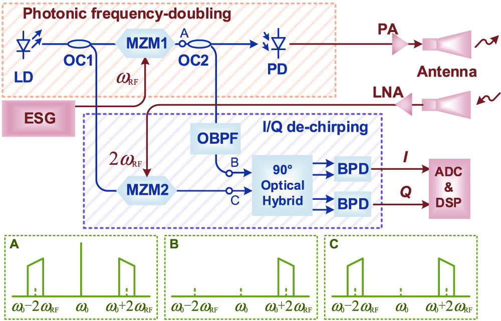
Figure 1.Schematic diagram of the proposed photonics-based radar. LD, laser diode; ESG, electrical signal generator; OC, optical coupler; MZM, Mach–Zehnder modulator; OBPF, optical bandpass filter; PA, power amplifier; LNA, low-noise amplifier; PD/BPD, (balanced) photodetector; ADC, analog-to-digital conversion; DSP, digital signal processing. (Insets, optical spectra at several key points in the system.)
The radar echo collected by the receiving antenna is first amplified by a low-noise amplifier (LNA) and then applied to modulate the optical carrier from the lower branch of OC1, at another MZM (MZM2). Here, MZM2 is biased at the null transmission point. After MZM2, the st-order sidebands would be located around , as shown in the right inset of Fig. 1. Assuming that the time delay between the radar echo and the transmitted signal is , the optical signal after MZM2 can be expressed as where is the modulation index. Then, the obtained optical signal and the optical LO signal are sent to a 90° optical hybrid. The four output signals of the optical hybrid are After the optical hybrid, two BPDs are applied to perform the optical-to-electrical conversion. The two obtained electrical signals are As can be seen, two single-tone signals with a phase difference of 90° are obtained, i.e., de-chirping of the radar echo in the I and Q channels is implemented. After analog-to-digital conversion, the two signals are combined digitally to get a complex signal given by The de-chirped signal in Eq. (7) has a frequency of , which is proportional to the time delay of the radar echo. In the digital signal processing (DSP) unit, by performing a fast Fourier transform (FFT) on the obtained complex signal, the de-chirped frequency can be acquired, so the time delay of the radar echo () as well as the target distance can be estimated [30]. By further employing the Doppler frequency information between adjacent radar pulses, 2D radar imaging can be conducted [31].
Since the range resolution of a radar is determined by the signal bandwidth, the proposed photonics-based radar system can achieve an improved range resolution thanks to the frequency-doubling property. Besides, the proposed radar is capable of determining the sign of the de-chirped frequency, which leads to an interference-free detection of targets on the two sides of a reference point. In practical applications, when detecting objects far away from the radar, a reference time delay () will be introduced to cancel part of the time delay of the radar echoes [28], i.e., where is the distance between the target and the radar, and is the speed of the electromagnetic wave. Thus, a low de-chirped frequency can be obtained that falls in the bandwidth of the receiver. This operation leads to the existence of a reference distance of . The target with a distance smaller than results in a negative de-chirped frequency, while the target having a distance exceeding generates a positive de-chirped frequency. In previously reported photonics-based radars applying real-valued de-chirping, only or in Eq. (6) is achieved. In the spectrum, the image-frequency interference makes it impossible to distinguish the targets on the two sides of the reference point. This problem can be solved with the proposed radar with photonics-based I/Q detection because the image-rejected spectrum of the complex-valued signal is single-sided.
The use of balanced detection also brings other advantages. First, the baseband or background interference of the de-chirped signal can be suppressed by balanced detection, as indicated by Eqs. (6) and (7). Thus, interference-free detection of the targets close to can be achieved by removing the strong interference in the low-frequency region. Besides, according to Ref. [34], balanced detection can enhance the power of the desired de-chirped signal by 6 dB compared with the case using single-end detection, which is favorable to improving the signal-to-noise ratio. Moreover, balanced detection can suppress undesired frequency-mixing components. Specifically, the radar echoes reflected from different targets lead to multiple modulation sidebands. The photonic frequency-mixing component between either two of these sidebands would produce false targets and cause interference in the detection of real targets. By using balanced detection, this problem can be solved because the frequency-mixing components of these modulation sidebands are in-phase between the two input ports of each BPD, and they can be canceled by balanced detection.
It is worthwhile to note that the proposed photonic radar transceiver can be further improved with only minor changes. For instance, in the transmitter, frequency quadrupling of the IF signal could be implemented by replacing the MZM with a dual-parallel MZM (DPMZM), of which the main MZM and the two sub-MZMs are all biased at the maximum transmission points and the two sub-MZMs are driven by the IF signal and its quadrature replica, respectively [35]. In addition, the function of the OBPF, which removes the nd-order or the nd-order sidebands to avoid the signal neutralization, could also be realized on the lower branch in the receiver. In doing so, a DPMZM working in the single sideband with a suppressed carrier mode can be utilized to simultaneously realize the electro-optical conversion and the sideband selection.
3. EXPERIMENT AND RESULTS
To investigate the performance of the proposed photonics-based radar, an experiment is carried out based on the setup in Fig. 1. The light from the laser source (TeraXion PureSpectrum-NLL, linewidth 5 kHz) is equally split into two branches by OC1, which is a 50:50 OC. In the transmitter, MZM1 (Fujitsu FTM7938, bandwidth ) is biased at the peak transmission point and driven by an IF-LFM signal generated by an arbitrary waveform generator (Tektronix AWG70000). The frequency, period, and duty ratio of the IF-LFM signal are 9–13 GHz, 20 μs, and 50%, respectively. The dotted blue line in Fig. 2 shows the optical spectrum of the signal at point A, which is measured by an optical spectrum analyzer (Yokogawa AQ6370C). As can be seen, two nd-order modulation sidebands are generated, which coexist with the optical carrier. After MZM1, the optical signal is split into two branches by a 5:95 OC (OC2). The majority part of the optical power is directed to a PD (Finisar XPDV2120) to generate the frequency-doubled LFM signal with a bandwidth of 8 GHz (18–26 GHz). This LFM signal is filtered by a K-band EBPF and then amplified by an electrical amplifier before being sent to a K-band horn antenna for radiation.

Figure 2.Optical spectra at several key points in the proposed photonic radar. Dotted blue line, output of the MZM in the transmitter (point A); solid red line, output of the OBPF (point B); dashed green line, output of the MZM in the receiver (point C).
To check the frequency-doubling capability of the transmitter, the waveforms of the IF-LFM signal and the generated LFM signal after the EBPF are captured by a real-time oscilloscope (Keysight 93304, bandwidth 33 GHz, maximum sampling rate 80 GSa/s). Spectrograms of the two signals are calculated by performing a short-time Fourier transform on the recorded data. The results are shown in Figs. 3(a) and 3(b), where the power profiles in the time domain and frequency domain are also plotted. As shown in Fig. 3, an 18–26 GHz LFM signal having the same pulse width as that of the 9–13 GHz IF-LFM signal is generated. In Fig. 3(b), some in-band spurs coexist with the 18–26 GHz LFM signal. The maximum spur is at 19.5 GHz, which is the sum frequency of the IF-LFM signal with its image frequency with respect to a 9.75 GHz clock signal. Since the chirp slopes of the spurs are different from the LFM signal in need, the spur-induced deterioration of the radar system can be neglected in the experiment.
Figure 3.Spectrograms of the signals (a) before and (b) after the photonic frequency doubling in the transmitter. The power profiles are projected to the time and frequency domains.
In the receiver, the optical LO signal is derived by passing the other optical signal from OC2 to an OBPF (Yenista XTM-50) to select one of the second-order modulation sidebands. Before sent to the OBPF, the optical signal power is boosted by an erbium-doped fiber amplifier (EDFA). The spectrum of the obtained optical LO signal is shown by the solid red line in Fig. 2, in which the optical carrier and the undesired modulation sideband are well suppressed. Meanwhile, the radar echo collected by another K-band horn antenna is amplified by an LNA with an operational frequency range of 17–31 GHz and then applied to MZM2 (Fujitsu FTM7938, bandwidth ) to modulate the optical carrier. MZM2 is biased at the null transmission point to perform double-sideband carrier-suppressed modulation, and the optical spectrum after MZM2 is shown by the dashed green line in Fig. 2. To implement photonic frequency mixing, a 90° optical hybrid (Kylia COH28) and two BPDs (Thorlabs PDB450C-AC, bandwidth 150 MHz) are applied. The obtained electrical signals are simultaneously sampled by two channels of the real-time oscilloscope, with a sampling rate of 40 MSa/s in each channel. The relative time delay between the radar echo and the transmitted signal is adjusted by a variable optical delay line to let the reference distance of the radar be .
To investigate the performance of the radar receiver, detection of two corner reflectors (size: ) is implemented by the proposed radar. The distance of the two corner reflectors from the radar is 116 and 131 cm, respectively. Figures 4(a) and 4(b) show the waveforms of the de-chirped I and Q signals. By performing FFT, the spectra are obtained and shown in Figs. 4(c) and 4(d), respectively. To manifest the advantage of balanced detection, waveforms and spectra of I and Q signals acquired by single-end detection are also included in Fig. 4. Here, the single-end detection results are obtained by disconnecting one input port of each BPD. In Figs. 4(a) and 4(b), the baseband envelope of the time-domain waveforms is clearly observed when using single-end detection. By applying balanced detection, the baseband envelopes are effectively suppressed. From the spectra in Figs. 4(c) and 4(d), the suppression ratios are 37 and 31 dB for the I and Q channels, respectively. The two spectral peaks in Figs. 4(c) and 4(d) at 3.67 and 4.5 MHz are the de-chirped frequencies corresponding to the two corner reflectors. Compared with the spectra obtained by single-end detection, the power enhancement of the de-chirped signals with balanced detection is for the I channel and for the Q channel. Due to the amplitude imbalance between the two channels, this improvement slightly deviates from the theoretical value (6 dB). Nevertheless, the advantage of balanced detection can still be confirmed. In addition, the suppression of frequency components due to frequency mixing between radar echoes using balanced detection can also be verified by the results in Figs. 4(c) and 4(d). In the spectra obtained by single-end detection, there are strong frequency components at , corresponding to the frequency difference between two de-chirped signals. Harmonics of this frequency are also generated because of the nonlinearity of the built-in electrical amplifiers in the BPDs. When applying balanced detection, these undesired frequency components are suppressed by over 30 dB. This property is particularly favorable toward improving the radar performance.
Figure 4.Comparison between the de-chirped signals obtained by single-end PD (SPD, dotted blue line) and BPD (solid red line), including time-domain waveforms of (a) the I channel and (b) the Q channel, and the corresponding spectra of (c) the I channel and (d) the Q channel by FFT.
Figure 5(a) shows the waveforms from the I and Q channels obtained by balanced detection in a temporal duration of 4 μs. As can be seen, the two signals have the same envelope, and the phase difference between the two signals is 90°, which indicates that I/Q detection is perfectly implemented. When combining the two signals to a complex signal, to compensate for the I/Q imbalance and phase mismatch, an algorithm is applied with the relationship between the original and the corrected signals given by [36] where is the amplitude imbalance and is the phase mismatch. In our experiment, and are estimated to be 0.7 dB and 2.3°, respectively, in which iterative searching for the values of and by maximizing the image-rejection ratio is utilized. The obtained complex signal has a single-sided spectrum, as shown by the solid red line in Fig. 5(b). Since the distances of the two targets from the radar are less than the reference distance, two negative de-chirped frequencies at and are observed. Thanks to the correction according to Eq. (9), a 4-dB improvement on the image-rejection ratio is achieved, and the final image-rejection ratio is 32 dB, as annotated in Fig. 5(b). As a comparison, the spectrum of the real-valued signal in the I channel is also calculated and shown by the dotted blue line in Fig. 5(b), in which the frequency components at and are generated. This result indicates the uncertainty of the target distance relative to the reference distance using real-valued de-chirping.
Figure 5.Results of the photonic I/Q radar receiver. (a) Zoom-in view of the captured waveforms; (b) spectra of the real de-chirped signal from the I channel and the combined complex de-chirped signal; (c) and (d) zoom-in views of the spectra around the peaks for indicating the range resolution of the proposed photonic radar.
Based on the spectrum in Fig. 5(b), the range resolution of the photonics-based radar is analyzed. Since each corner reflector can be treated as a single scattering point, the de-chirped complex spectrum can be considered as a one-dimensional point spread function (PSF). As shown by the zoom-in views in Figs. 5(c) and 5(d), the 3-dB widths of the two spectral peaks around and are 0.102 and 0.105 MHz, respectively. The range resolution calculated according to these two spectral widths is 1.91 and 1.97 cm, respectively. The results are very close to the theoretical range resolution of 1.875 cm, which is determined by the signal bandwidth [30].
Then, turntable ISAR imaging is implemented to further highlight the superiority of the proposed photonics-based radar with I/Q reception. Figure 6(a) is a picture of the experimental setup, and Fig. 6(b) shows the rotator with two corner reflectors as the targets. The rotating speed of the rotator is rad/s, and the center of the rotator is chosen as the reference point. The integration time in constructing the ISAR images is set to 0.056 s to obtain an ISAR viewing angle of 20°, which corresponds to a cross-range resolution of . Figures 6(c)–6(e) show the ISAR images constructed using the I channel, the Q channel, and the complex signal separately. In Figs. 6(c) and 6(d), four targets are observed, of which two false targets are generated due to the frequency ambiguity in real-valued de-chirp processing. In contrast, the ISAR image obtained based on the complex signal suffers from no false targets, as shown in Fig. 6(e). The ISAR demonstration reveals the significance of the I/Q reception in the suppression of the false targets caused by image frequency. Such suppression is especially essential for imaging a large region, in which case it is impossible to avoid image frequency by simply setting the reference point of the radar to let the reflective targets only exist on one side of the reference point.
Figure 6.(a) and (b) Experimental setup, and (c)–(e) results of the ISAR demonstration.
Although the proposed radar is only tested with the reference distance set to , its range can be easily extended using the proposed transceiver structure. On the one hand, an extended radar range requires a remote reference distance. This can be realized by increasing the time delay of the optical LO signal. The distinctive advantage of low loss in the optical fiber delay line could thereby be exploited. On the other hand, the range between the minimum and the maximum distance that can be processed by the receiver should also be extended. According to Eq. (8), the frequency of the de-chirped echo is proportional to the interval between the target and the reference distance. Thus, a digital receiver with a larger analog-to-digital conversion bandwidth should be applied to satisfy the requirement of an extended range. Optionally, since the proposed photonic radar could realize image-free ranging by I/Q reception, a large range could also be synthesized by establishing parallel multiple receivers with different reference distances.
4. DISCUSSION AND CONCLUSION
It is worthwhile to mention that the implementation of I/Q de-chirping through photonic methods could also lead to drawbacks when compared to electronic mixers, especially for the noise performance, which is degraded by the loss in the electro-optical and optical-electrical conversion as well as the EDFA used in the receiver. Fortunately, the influence of the photonics-induced noise could be minimized if an LNA with a high gain is applied in front of the photonic de-chirp processor, in which case the noise figure of the entire receiver is dominated by the LNA. In addition, the OBPF after the EDFA can also help to suppress the noise by removing the out-of-band amplified spontaneous emission noise.
In the proposed I/Q detection scheme, the wavelength stability of the laser may influence the coherence of the radar by introducing phase dither to the de-chirped complex signal [37]. To show the influence of the laser wavelength stability, we compare the ISAR imaging results by applying laser sources with different wavelength dithers. Figure 7(a) shows the ISAR image of a single corner reflector when the system applies an LD with a wavelength dither less than 2 fm. In this case, the wavelength change of the laser can be neglected during the integration time in constructing the ISAR image. No obvious influence on the ISAR imaging results is observed. Figure 7(b) shows the ISAR image of the same target when another LD (Agilent N7714A) with a wavelength dither range of is used. Owing to the interferometer-like structure of the proposed receiver, the wavelength dither can lead to observable phase dither on the de-chirped complex signal, especially when the differential delay between the two optical branches is not perfectly compensated. Thus, the Doppler frequency estimation between adjacent pulses could deteriorate, which results in the blur in the azimuth direction of the image, as is shown in Fig. 7(b).
Figure 7.ISAR imaging results when using a laser source with (a) -fm wavelength dither and (b) 800-fm wavelength dither.
To further investigate the effect of the laser wavelength stability, we simulate the ISAR imaging of a point target under different laser wavelength dithers and different uncompensated differential delays between two branches. The quality of the constructed ISAR image is evaluated by a figure of merit (FoM), which is defined by the ratio of azimuth width of the two-dimensional PSF under a perfectly stabilized laser to the azimuth width under dithering lasers. Since the laser wavelength dither-induced blur can broaden the azimuth width of the image, a higher FoM can be obtained when applying a laser with better wavelength stability. The simulation results are summarized as the contour plot in Fig. 8, in which ISAR images under four typical conditions are also illustrated as the insets A, B, C, and D. We can see that the increase of both the wavelength dither and the differential delay can degrade the ISAR results in terms of the azimuth resolution. If we set the condition of , which means the azimuth resolution degradation is less than 50% as the requirement for an acceptable image, the region under the contour line at 0.5 in Fig. 8 is the feasible region for wavelength dither and differential delay. By hyperbolic fit of this contour line, we can assume that the product of the laser wavelength dither range and the uncompensated differential delay between two branches should be less than 201.4 (ns·pm).
Figure 8.Simulated results on the FoM of the image with different laser wavelength dithers and different uncompensated differential delays between two branches. The hyperbolic fit of the contour line at 0.5, which is considered as the threshold of the acceptable imaging, is plotted as the dotted blue line. Images under four typical conditions at points A, B, C, and D are also depicted as the insets.
In conclusion, we have demonstrated a photonics-based broadband radar with frequency doubling and balanced I/Q de-chirping detection, aiming to achieve a large operation bandwidth and remove the interference in traditional photonic de-chirping receivers with single-channel real-valued photonic frequency mixing. A photonics-based K-band radar with a bandwidth of 8 GHz was established and investigated. Through detection and imaging of different targets, advantages of the proposed radar were demonstrated. The proposed system would provide an effective way to improve the performance of a photonics-based radar in practical operation.
Acknowledgment
Acknowledgment. The authors would like to thank Ziqian Wang for providing the BPDs.
References
[1] M. I. Skolnik. An introduction and overview of radar. Radar Handbook, 1.1-1.24(2008).
[2] M. Cheney, B. Borden. The radar ambiguity function. Fundamentals of Radar Imaging, 35-48(2008).
[3] S. Pan, J. Yao. Photonics-based broadband microwave measurement. J. Lightwave Technol., 35, 3498-3513(2017).
[4] S. Pan, D. Zhu, S. Liu, K. Xu. Satellite payloads pay off. IEEE Microw. Mag., 16, 61-73(2015).
[5] Y. Li, A. Rashidinejad, J.-M. Wun, D. E. Leaird, J.-W. Shi, A. M. Weiner. Photonic generation of W-band arbitrary waveforms with high time-bandwidth products enabling 3.9 mm range resolution. Optica, 1, 446-454(2014).
[6] S. Zhang, W. Zou, N. Qian, J. Chen. Enlarged range and filter-tuned reception in photonic time-stretched microwave radar. IEEE Photon. Technol. Lett., 30, 1028-1031(2018).
[7] S. Peng, S. Li, X. Xue, X. Xiao, D. Wu, X. Zheng, B. Zhou. High-resolution W-band ISAR imaging system utilizing a logic-operation-based photonic digital-to-analog converter. Opt. Express, 26, 1978-1987(2018).
[8] X. Wang, T. Niu, E. H. W. Chan, X. Feng, B. O. Guan, J. Yao. Photonics-based wideband microwave phase shifter. IEEE Photon. J., 9, 5501710(2017).
[9] I. Aryanfar, D. Marpaung, A. Choudhary, Y. Liu, K. Vu, D.-Y. Choi, P. Ma, S. Madden, B. J. Eggleton. Chip-based Brillouin radio frequency photonic phase shifter and wideband time delay. Opt. Lett., 42, 1313-1316(2017).
[10] Y. Zhang, S. Pan. Broadband microwave signal processing enabled by polarization-based photonic microwave phase shifters. IEEE J. Quantum Electron., 54, 0700112(2018).
[11] Z. Tang, S. Pan. Image-reject mixer with large suppression of mixing spurs based on a photonic microwave phase shifter. J. Lightwave Technol., 34, 4729-4735(2016).
[12] Z. Tang, S. Pan. A reconfigurable photonic microwave mixer using a 90° optical hybrid. IEEE Trans. Microw. Theory Tech., 64, 3017-3025(2016).
[13] Y. Gao, A. Wen, W. Zhang, W. Jiang, J. Ge, Y. Fan. Ultra-wideband photonic microwave I/Q mixer for zero-IF receiver. IEEE Trans. Microw. Theory Tech., 65, 4513-4525(2017).
[14] J. Li, J. Xiao, X. Song, Y. Zheng, C. Yin, Q. Lv, Y. Fan, F. Yin, Y. Dai, K. Xu. Full-band direct-conversion receiver with enhanced port isolation and I/Q phase balance using microwave photonic I/Q mixer. Chin. Opt. Lett., 15, 010014(2017).
[15] D. Zhu, W. Chen, S. Pan. Photonics-enabled balanced Hartley architecture for broadband image-reject microwave mixing. Opt. Express, 26, 28022-28029(2018).
[16] G. C. Valley. Photonic analog-to-digital converters. Opt. Express, 15, 1955-1982(2007).
[17] P. Ghelfi, F. Laghezza, F. Scotti, G. Serafino, A. Capria, S. Pinna, D. Onori, C. Porzi, M. Scaffardi, A. Malacarne, V. Vercesi, E. Lazzeri, F. Berizzi, A. Bogoni. A fully photonics-based coherent radar system. Nature, 507, 341-345(2014).
[18] X. Zhu, D. Zhu, S. Pan. A photonic analog-to-digital converter with multiplied sampling rate using a fiber ring. International Topical Meeting on Microwave Photonics (MWP), 1-3(2017).
[19] W. Li, W. T. Wang, W. H. Sun, W. Y. Wang, N. H. Zhu. Stable radio-frequency phase distribution over optical fiber by phase-drift auto-cancellation. Opt. Lett., 39, 4294-4296(2014).
[20] S. Pan, J. Wei, F. Zhang. Passive phase correction for stable radio frequency transfer via optical fiber. Photon. Netw. Commun., 31, 327-335(2016).
[21] D. Wang, T. Jiang, C. Liu, S. Zhou, S. Yu. Stable radio frequency dissemination via a 1007 km fiber link based on a high-performance phase lock loop. Opt. Express, 26, 24479-24486(2018).
[22] X. Ye, F. Zhang, S. Pan. Compact optical true time delay beamformer for a 2D phased array antenna using tunable dispersive elements. Opt. Lett., 41, 3956-3959(2016).
[23] X. Ye, D. Zhu, Y. Zhang, S. Li, S. Pan. Analysis of photonics-based RF beamforming with large instantaneous bandwidth. J. Lightwave Technol., 35, 5010-5019(2017).
[24] Z. G. Tegegne, C. Decroze, P. D. Bin, T. Fromenteze, C. Aupetit-Berthelemot. Single channel microwave photonics digital beamforming radar imaging system. J. Lightwave Technol., 36, 675-681(2018).
[25] Marki Microwave. Passive GaAs MMIC IQ mixer, MMIQ-0626H(2017).
[26] Analog Devices. Datasheet, HMC8191(2018).
[27] R. Li, W. Li, M. Ding, Z. Wen, Y. Li, L. Zhou, S. Yu, T. Xing, B. Gao, Y. Luan, Y. Zhu, P. Guo, Y. Tian, X. Liang. Demonstration of a microwave photonic synthetic aperture radar based on photonic-assisted signal generation and stretch processing. Opt. Express, 25, 14334-14340(2017).
[28] A. Wang, J. Wo, X. Luo, Y. Wang, W. Cong, P. Du, J. Zhang, B. Zhao, J. Zhang, Y. Zhu, J. Lan, L. Yu. Ka-band microwave photonic ultra-wideband imaging radar for capturing quantitative target information. Opt. Express, 26, 20708-20717(2018).
[29] Y. Yao, F. Zhang, Y. Zhang, X. Ye, D. Zhu, S. Pan. Demonstration of ultra-high-resolution photonics-based Ka-band inverse synthetic aperture radar imaging. Optical Fiber Communications Conference and Exposition (OFC), Th3G.5(2018).
[30] F. Zhang, Q. Guo, S. Pan. Photonics-based real-time ultra-high-range-resolution radar with broadband signal generation and processing. Sci. Rep., 7, 13848(2017).
[31] F. Zhang, Q. Guo, Z. Wang, P. Zhou, G. Zhang, J. Sun, S. Pan. Photonics-based broadband radar for high-resolution and real-time inverse synthetic aperture imaging. Opt. Express, 25, 16274-16281(2017).
[32] F. Zhang, Q. Guo, Y. Zhang, Y. Yao, P. Zhou, D. Zhu, S. Pan. Photonics-based real-time and high-resolution ISAR imaging of non-cooperative target. Chin. Opt. Lett., 15, 112801(2017).
[33] F. Zhang, B. Gao, S. Pan. Photonics-based MIMO radar with high-resolution and fast detection capability. Opt. Express, 26, 17529-17540(2018).
[34] F. Zhang, X. Ge, S. Pan. Background-free pulsed microwave signal generation based on spectral shaping and frequency-to-time mapping. Photon. Res., 2, B5-B10(2014).
[35] Y. Gao, A. Wen, W. Jiang, D. Liang, W. Liu, S. Xiang. Photonic microwave generation with frequency octupling based on a DP-QPSK modulator. IEEE Photon. Technol. Lett., 27, 2260-2263(2015).
[36] M. A. Richards. Pulsed radar data acquisition. Fundamentals of Radar Signal Processing, 183-229(2014).
[37] F. Zhang, Y. Li, J. Wu, W. Li, X. Hong, J. Lin. Improved pilot-aided optical carrier phase recovery for coherent M-QAM. IEEE Photon. Technol. Lett., 24, 1577-1580(2012).


