• Acta Optica Sinica
  • Vol. 39, Issue 2, 0213001 (2019)
Fangfang Shen*, Xinxin Su, Sicheng Yang, Zhenlin Wu, Mingshan Zhao, and Xiuyou Han*
Author Affiliations
  • School of Optoelectronic Engineering and Instrumentation Science, Dalian University of Technology, Dalian, Liaoning 116024, China
  • show less
    DOI: 10.3788/AOS201939.0213001 Cite this Article Set citation alerts
    Fangfang Shen, Xinxin Su, Sicheng Yang, Zhenlin Wu, Mingshan Zhao, Xiuyou Han. Design of Time Delay Network for Optical Beamforming Based on Anti-Resonant Waveguide Micro-Rings[J]. Acta Optica Sinica, 2019, 39(2): 0213001 Copy Citation Text show less
    Bandwidths for different time delay schemes. (a) Delay on two sidebands and optical carrier; (b) delay on one sideband and optical carrier; (c) delay on only one sideband
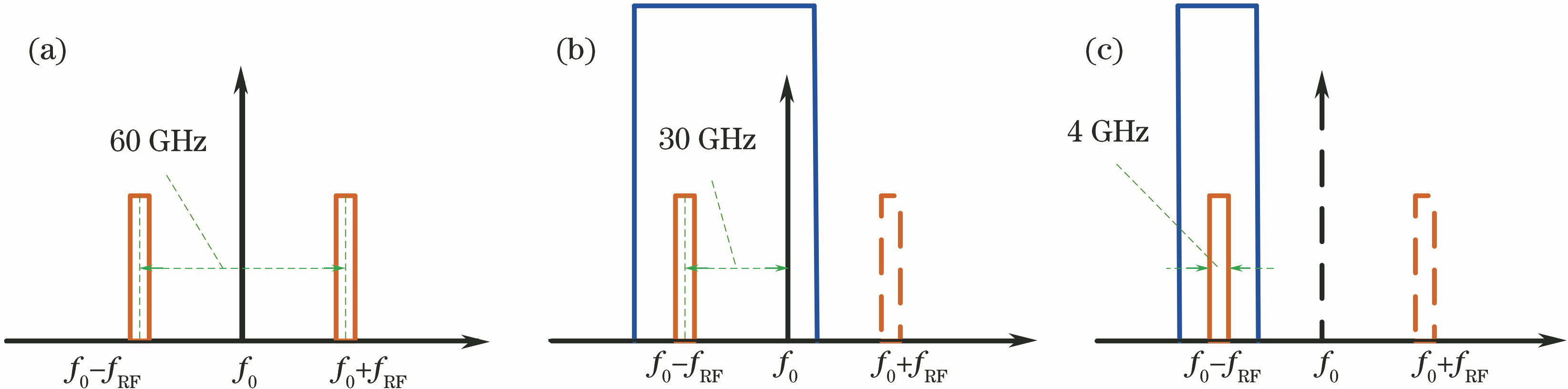
    Fig. 1. Bandwidths for different time delay schemes. (a) Delay on two sidebands and optical carrier; (b) delay on one sideband and optical carrier; (c) delay on only one sideband
    Structural diagram of optical time delay network
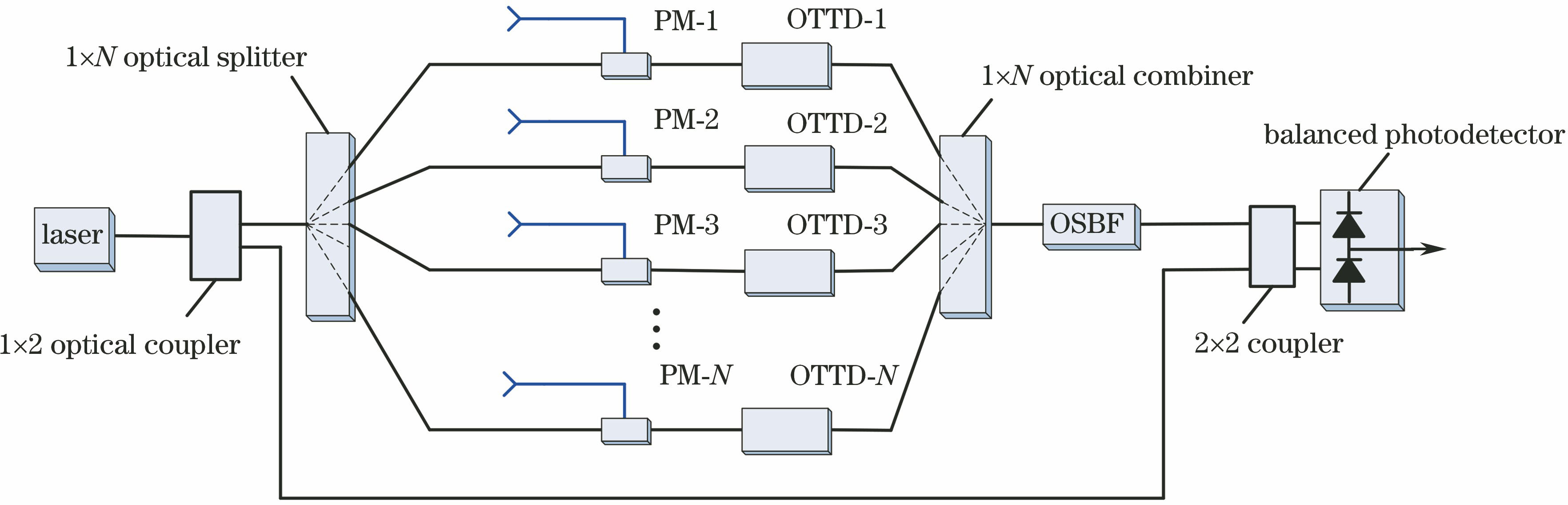
    Fig. 2. Structural diagram of optical time delay network
    Structure of antenna array. (a) Structure of one-dimensional linear array; (b) time delay network the fourth element linear array
    Fig. 3. Structure of antenna array. (a) Structure of one-dimensional linear array; (b) time delay network the fourth element linear array
    Intensity response of waveguide micro-rings with different loss coefficients at κ=0.3
    Fig. 4. Intensity response of waveguide micro-rings with different loss coefficients at κ=0.3
    Simulated time delay curve for each path of micro-ring with the maximum scan angle (+30°). (a) Simulated time delay response curves of each path for time delay network; (b) enlarged map of time delay response at anti-resonance
    Fig. 5. Simulated time delay curve for each path of micro-ring with the maximum scan angle (+30°). (a) Simulated time delay response curves of each path for time delay network; (b) enlarged map of time delay response at anti-resonance
    Structural diagram of micro-ring assisted MZI bandpass filter
    Fig. 6. Structural diagram of micro-ring assisted MZI bandpass filter
    Intensity response curves of bandpass filter
    Fig. 7. Intensity response curves of bandpass filter
    Target delay time versus loss under different propagation losses of waveguide
    Fig. 8. Target delay time versus loss under different propagation losses of waveguide
    Angleκ11,κ12κ21,κ22κ31,κ32κ41,κ42
    -30°00.3790.620.774
    +30°0.7740.620.3790
    Table 1. Coupling coefficients of micro-rings in time delay network at the maximum scanning angle
    Coupling coefficient deviation±1%±2%±3%±4%±5%
    Delay deviation /ps0.531.081.602.202.80
    Table 2. Time delay deviation value under different coupling coefficient deviations
    Ring loss factor αDelay-loss coefficient /(dB·ps-1)Gain /dBNoise figure /dB
    0.9929.96×10-4-30.936.5
    0.9610.00494-32.337.2
    0.9240.00983-34.138.2
    Table 3. Gain and noise coefficients of system link under different cycle loss factors
    Fangfang Shen, Xinxin Su, Sicheng Yang, Zhenlin Wu, Mingshan Zhao, Xiuyou Han. Design of Time Delay Network for Optical Beamforming Based on Anti-Resonant Waveguide Micro-Rings[J]. Acta Optica Sinica, 2019, 39(2): 0213001
    Download Citation