• Chinese Optics Letters
  • Vol. 18, Issue 7, 072401 (2020)
Zhanlei Hao, Yawen Zhuang, Ying Chen*, Yineng Liu**, and Huanyang Chen***
Author Affiliations
  • Institute of Electromagnetics and Acoustics and Key Laboratory of Electromagnetic Wave Science and Detection Technology, Xiamen University, Xiamen 361005, China
  • show less
    DOI: 10.3788/COL202018.072401 Cite this Article Set citation alerts
    Zhanlei Hao, Yawen Zhuang, Ying Chen, Yineng Liu, Huanyang Chen. Effective medium theory of checkboard structures in the long-wavelength limit[J]. Chinese Optics Letters, 2020, 18(7): 072401 Copy Citation Text show less
    (a) Square CS with a period a. (b) Rectangular CS with a period a along the x direction and a period b along the y direction. The permittivity of the yellow region and white region is ϵ1 and ϵ2, respectively.
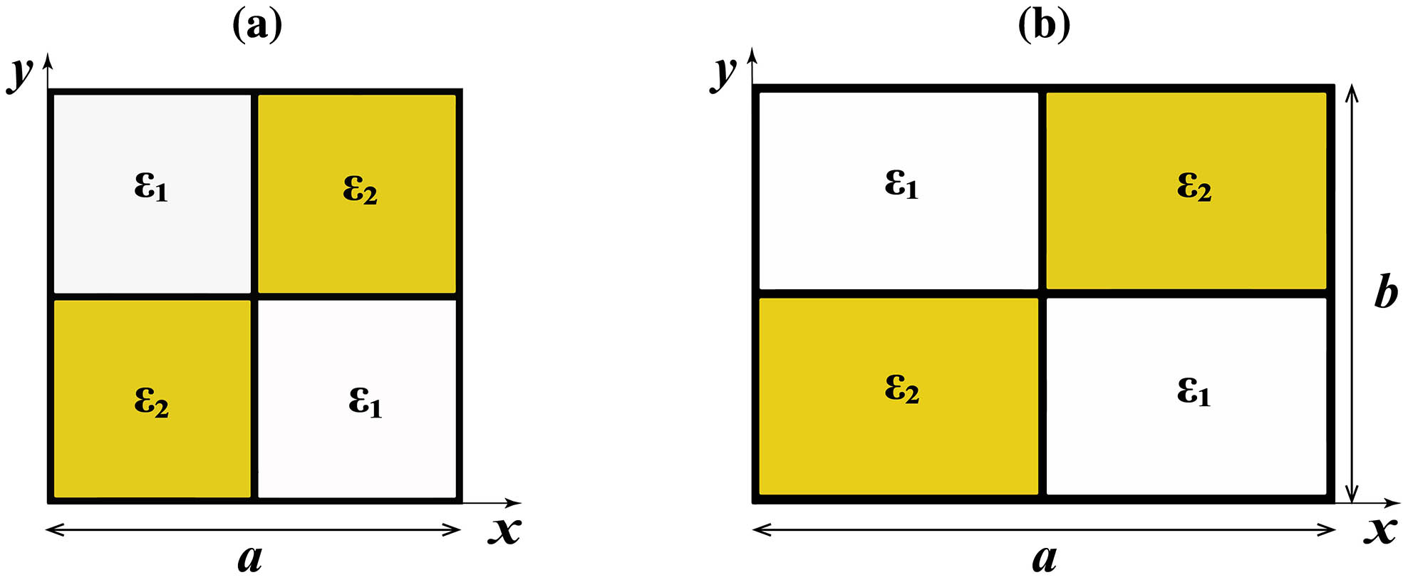
    Fig. 1. (a) Square CS with a period a. (b) Rectangular CS with a period a along the x direction and a period b along the y direction. The permittivity of the yellow region and white region is ϵ1 and ϵ2, respectively.
    The field patterns Hz when incident with (a) a plane wave and (c) a point source on a square CS, with 50×50 unit cells in the middle (only the sketch is shown here). The period a is set as 200 nm, with ϵ1=4 and ϵ2=1. (b), (d) Field patterns when using the isotropic and uniform medium in the middle region.
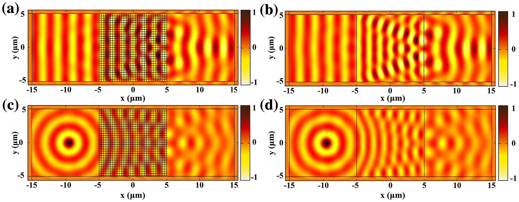
    Fig. 2. The field patterns Hz when incident with (a) a plane wave and (c) a point source on a square CS, with 50×50 unit cells in the middle (only the sketch is shown here). The period a is set as 200 nm, with ϵ1=4 and ϵ2=1. (b), (d) Field patterns when using the isotropic and uniform medium in the middle region.
    The field patterns Hz when incident with (a) a plane wave and (c) a point source to the middle bulk material composed with rectangular CS. The middle region of the effective medium has 50×100 unit cells (only the sketch is shown here), with a=200 nm, b=100 nm, ϵ1=4, and ϵ2=1. (b), (d) Field patterns when using the anisotropic and uniform medium.
    Fig. 3. The field patterns Hz when incident with (a) a plane wave and (c) a point source to the middle bulk material composed with rectangular CS. The middle region of the effective medium has 50×100 unit cells (only the sketch is shown here), with a=200nm, b=100nm, ϵ1=4, and ϵ2=1. (b), (d) Field patterns when using the anisotropic and uniform medium.
    Field patterns Hz when (a) a plane wave and (c) a cylindrical wave pass through a gradient circular ring. The circular grids (only the sketch is shown here) are formed by many sector units in the CS, including 10 (r)×24 (θ) unit cells. Inner and outer radii of this ring are 1 μm and 4 μm, and we keep the permittivity of ϵ1=4 and ϵ2=1 unchanged in each unit cell. (b), (d) Field patterns when using a gradient and anisotropic medium incident by (b) a plane wave or (d) a point source, where the same layers along the radial direction are set.
    Fig. 4. Field patterns Hz when (a) a plane wave and (c) a cylindrical wave pass through a gradient circular ring. The circular grids (only the sketch is shown here) are formed by many sector units in the CS, including 10(r)×24(θ) unit cells. Inner and outer radii of this ring are 1 μm and 4 μm, and we keep the permittivity of ϵ1=4 and ϵ2=1 unchanged in each unit cell. (b), (d) Field patterns when using a gradient and anisotropic medium incident by (b) a plane wave or (d) a point source, where the same layers along the radial direction are set.
    ϵ1/ϵ2a/b
    4210.80.650.5
    5ϵx=3.170ϵx=2.604ϵx=2.236ϵx=2.173ϵx=2.101ϵx=1.946
    ϵy=1.810ϵy=1.946ϵy=2.236ϵy=2.368ϵy=2.463ϵy=2.605
    4.5ϵx=2.837ϵx=2.411ϵx=2.117ϵx=2.021ϵx=1.949ϵx=1.838
    ϵy=1.780ϵy=1.839ϵy=2.117ϵy=2.219ϵy=2.307ϵy=2.411
    4ϵx=2.650ϵx=2.218ϵx=2.017ϵx=1.919ϵx=1.891ϵx=1.733
    ϵy=1.719ϵy=1.733ϵy=2.017ϵy=2.087ϵy=2.155ϵy=2.218
    3ϵx=2.131ϵx=1.832ϵx=1.696ϵx=1.650ϵx=1.605ϵx=1.522
    ϵy=1.568ϵy=1.521ϵy=1.696ϵy=1.767ϵy=1.818ϵy=1.832
    2.5ϵx=1.871ϵx=1.639ϵx=1.564ϵx=1.517ϵx=1.483ϵx=1.415
    ϵy=1.463ϵy=1.415ϵy=1.564ϵy=1.607ϵy=1.645ϵy=1.639
    2ϵx=1.611ϵx=1.446ϵx=1.414ϵx=1.395ϵx=1.392ϵx=1.308
    ϵy=1.357ϵy=1.308ϵy=1.414ϵy=1.447ϵy=1.453ϵy=1.446
    1.5ϵx=2.654ϵx=2.521ϵx=2.451ϵx=2.427ϵx=2.396ϵx=2.353
    ϵy=2.275ϵy=2.353ϵy=2.451ϵy=2.457ϵy=2.496ϵy=2.525
    Table 1. Effective Permittivity ϵx and ϵy Obtained from the Slopes along ΓX and ΓY Directions in the Band Structure, While Keeping ϵ1/ϵ2 Unchanged for Each Row and Tuning the Ratios of a/b from 0.5 to 4
    ϵa/b
    11.251.541.802.102.332.572.883.103.33
    ϵx2.0012.0932.1712.2392.2992.3532.4032.4482.4912.530
    ϵy1.9991.9111.8421.7871.7401.7001.6651.6341.6061.581
    Table 2. Fitted Anisotropic Permittivity ϵx and ϵy of the Circular Ring Material Based on Eq. (3), Where the Permittivity ϵ1=4 and ϵ2=1 Are Kept Unchanged in Each Unit Cell
    Zhanlei Hao, Yawen Zhuang, Ying Chen, Yineng Liu, Huanyang Chen. Effective medium theory of checkboard structures in the long-wavelength limit[J]. Chinese Optics Letters, 2020, 18(7): 072401
    Download Citation