Abstract
Effective medium theory is a powerful tool to solve various problems for achieving multifarious functionalities and applications. In this article, we present a concise empirical formula about effective permittivity of checkboard structures for different directions. To verify our empirical formula, we perform simulations of checkboard periodic structures in squares, rectangles, and sectors in two dimensions. Our results show that the formula is valid in a large range of parameters. This work provides a new way to understand and design composite materials, which might lead to further optical applications in transformation optics.Effective medium theory (EMT)[1] can achieve similar functions of overall systems by defining material averages with effective parameters. There are two famous theories of effective medium approaches, i.e., the Maxwell–Garnett theory (MGT)[2] and the Bruggeman EMT (BEMT)[3], which are both based on material characteristics of each component in the mixture. Depending on the relative concentration of the inclusions and the difference in the manufacturing process, the composition of metals and dielectric materials exhibits different structural properties[1,4]. EMT provides many applications in material composites, such as to describe anistropic media[5,6], optical properties[7–9], and conductivity properties[10].
Recently, Pendry et al. and Leonhardt proposed the concept of transformation optics (TO) by using the coordinate invariance principle of Maxwell’s equations and the method of coordinate transformations in mathematics[4,11,12]. Combining TO with EMT, we can realize a series of transformation optical devices, such as cloaking[13,14], field rotators[15–17], and field concentrators[18–20]. Most of them are either with very complicated structures and not able to be designed analytically/semi-analytically, or with a layered system, and the effective material parameters are limited. In this article, we will explore anisotropic checkboard structures (CSs), which will provide an alternative choice for future TO designs.
In the past two decades, there has been a strong revival of interest in checkboard problems focused mostly on conductivity[21] and effective permittivity[22–24]. Various classical mixing rules and matrix methods are proposed to estimate the characteristics of mixtures, and they are often used beyond their area of applicability. In this work, we discretize two kinds of materials with unequal permittivities into unit cells and arrange them in a staggered layout as a checkboard-like structure. Based on EMT, we use the band theory of the structure to get an empirical formula of effective permittivities for different directions. From numerical simulations, we demonstrate that the EMT for the CSs is valid for unit cells in squares, rectangles, and sectors in the same framework for various material parameters.
Sign up for Chinese Optics Letters TOC. Get the latest issue of Chinese Optics Letters delivered right to you!Sign up now
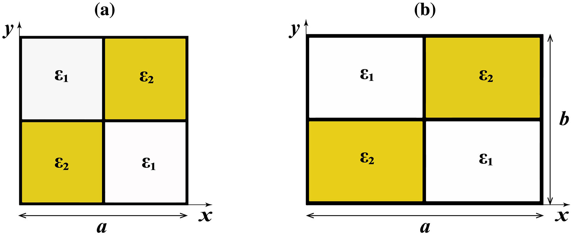
Let us start from a two-dimensional CS, which is composed of alternately arranged small squares along the and directions, as shown in Fig. 1(a), for a unit cell. The lattice period is , while the two isotropic materials have permittivity (the white square) and (the yellow square), respectively. It is easy to derive the effective medium of such a periodic checkboard composite, which is expected to be isotropic due to the symmetric structure[21]. Considering the transverse electric (TE) modes (, , ) without external electric current and charge, the equations of electrostatics are , , and . Defining another set of vectors and , we see that they also satisfy the above equations: where for the white region, and for the yellow region. Due to the symmetry of these two media, we can obtain that and . Besides, the relation is also established. Thus, the effective medium of such a CS is extracted as

Figure 1.(a) Square CS with a period . (b) Rectangular CS with a period along the direction and period along the direction. The permittivity of the yellow region and white region is and , respectively.
However, when it comes to the anisotropic case of the rectangle checkboard in Fig. 1(b), the above formula is not applicable. Here, we numerically obtain an empirical formula for the effective medium for this anisotropic structure, where the period along the direction is , while that along the direction is . For the periodic rectangle CS, we can plot the band structure, where the dispersive bands along and tend to linearity in the long-wavelength region. From the slope of the lowest bands in the band structure, we can thus extract the effective permittivity along the and directions as and , respectively, as shown in Table 1. For example, for the parameters of and , the anisotropic permittivity can be found when is not equal to 1, which results from the structural asymmetry along the and directions. When , the permittivity turns to an isotropic material, i.e.,, which can also be obtained from Eq. (2).Based on plenty of account data, we can obtain an empirical formula to describe an effective permittivity tensor of such a CS, which is related to the parameters , , , and ,
| ϵ1/ϵ2 | a/b |
|---|
| 4 | 2 | 1 | 0.8 | 0.65 | 0.5 |
|---|
| 5 | ϵx=3.170 | ϵx=2.604 | ϵx=2.236 | ϵx=2.173 | ϵx=2.101 | ϵx=1.946 |
| ϵy=1.810 | ϵy=1.946 | ϵy=2.236 | ϵy=2.368 | ϵy=2.463 | ϵy=2.605 |
| 4.5 | ϵx=2.837 | ϵx=2.411 | ϵx=2.117 | ϵx=2.021 | ϵx=1.949 | ϵx=1.838 |
| ϵy=1.780 | ϵy=1.839 | ϵy=2.117 | ϵy=2.219 | ϵy=2.307 | ϵy=2.411 |
| 4 | ϵx=2.650 | ϵx=2.218 | ϵx=2.017 | ϵx=1.919 | ϵx=1.891 | ϵx=1.733 |
| ϵy=1.719 | ϵy=1.733 | ϵy=2.017 | ϵy=2.087 | ϵy=2.155 | ϵy=2.218 |
| 3 | ϵx=2.131 | ϵx=1.832 | ϵx=1.696 | ϵx=1.650 | ϵx=1.605 | ϵx=1.522 |
| ϵy=1.568 | ϵy=1.521 | ϵy=1.696 | ϵy=1.767 | ϵy=1.818 | ϵy=1.832 |
| 2.5 | ϵx=1.871 | ϵx=1.639 | ϵx=1.564 | ϵx=1.517 | ϵx=1.483 | ϵx=1.415 |
| ϵy=1.463 | ϵy=1.415 | ϵy=1.564 | ϵy=1.607 | ϵy=1.645 | ϵy=1.639 |
| 2 | ϵx=1.611 | ϵx=1.446 | ϵx=1.414 | ϵx=1.395 | ϵx=1.392 | ϵx=1.308 |
| ϵy=1.357 | ϵy=1.308 | ϵy=1.414 | ϵy=1.447 | ϵy=1.453 | ϵy=1.446 |
| 1.5 | ϵx=2.654 | ϵx=2.521 | ϵx=2.451 | ϵx=2.427 | ϵx=2.396 | ϵx=2.353 |
| ϵy=2.275 | ϵy=2.353 | ϵy=2.451 | ϵy=2.457 | ϵy=2.496 | ϵy=2.525 |
Table 1. Effective Permittivity and Obtained from the Slopes along and Directions in the Band Structure, While Keeping Unchanged for Each Row and Tuning the Ratios of from 0.5 to 4
Notedly, the empirical formula in Eq. (3) is effective only for the ranges of and . For other ratios beyond the ranges, further fittings are needed. Besides, the above two effective medium formulas [Eqs. (2) and (3)] are consistent with each other under the long-wavelength limit, i.e., the wavelength is much larger than the period of the CS. In the following, we will further verify the validity of the above EMT in the CS. All the finite element simulation results are obtained using COMSOL Multiphysics.
For the simplest case of square CS, we design a supercell to study its effective medium effect under normal and oblique incidence, as shown in Figs. 2(a) and 2(c). The middle grid represents this bulk material composed of periodic CS, where the period is set as 200 nm, and and . Based on Eq. (2), the effective medium of this bulk material is . The background materials on both sides are set as air with in all the simulations. Firstly, we use a plane wave with a wavelength of incident on the square CS, and the field patterns are displayed in Fig. 2(a). When replacing the CS with an isotropic bulk material of , the magnetic fields can be found in Fig. 2(b). Obviously, we can see that the pattern is highly consistent with that in Fig. 2(a), both in the middle equivalent area and other output regions. Considering the compatibility of Eq. (2) under oblique incidence, in Figs. 2(c) and 2(d) a cylindrical wave is emitted from the left side, which then passes through the square CS [Fig. 2(c)] or the effective isotropic medium of [Fig. 2(d)]. The results also show consistency in both field patterns and verify the validity of the isotropic EMT in the square CS.
Figure 2.The field patterns when incident with (a) a plane wave and (c) a point source on a square CS, with unit cells in the middle (only the sketch is shown here). The period is set as 200 nm, with and . (b), (d) Field patterns when using the isotropic and uniform medium in the middle region.
For the rectangular CS in Fig. 1(b), the anisotropic effective medium formula has been numerically obtained in Eq. (3). Here, we will give a similar analysis of its effectiveness under a plane wave and a point source incidence. In Figs. 3(a) and 3(c), the middle grid contains unit cells; each is a rectangle in Fig. 1(b) with , , , and . According to Eq. (3), we can get the anisotropic material with the principal values of the effective permittivity tensor of this middle CS as , . Figures 3(a) and 3(c) display the magnetic fields when a plane wave and a cylindrical wave with passes through the bulk checkboard material. The comparisons are shown in Figs. 3(b) and 3(d) with anisotropic and uniform medium with , in the middle region. We can see that the field patterns are almost the same, which illustrates that the fitted empirical formula in Eq. (3) is efficient for the anisotropic rectangle CS.
Figure 3.The field patterns when incident with (a) a plane wave and (c) a point source to the middle bulk material composed with rectangular CS. The middle region of the effective medium has unit cells (only the sketch is shown here), with , , , and . (b), (d) Field patterns when using the anisotropic and uniform medium.
In Fig. 4, we further consider a gradient circular ring material realized by the rectangular CS. By changing the ratio of gradually, the anisotropic and gradient materials can be obtained. As shown in the grid in Fig. 4(a), the inner and outer radii of this ring are 1 μm and 4 μm, respectively, and we separate it into 20 uniform layers along the radial direction () and 48 layers along the rotation direction. Since the sector unit is small enough, we can treat each piece as a rectangle. Here, we retain the permittivity of and unchanged in each unit cell, and the effective media are then extracted from Table 2 for different ratios of . We can see that for the approximate ratio of at , the anisotropy of this circular ring material is very small and the material is close to the isotropy medium with . With the increase of , the anisotropy between and becomes larger, i.e., increases from 2.001 to 2.53, while decreases from 1.999 to 1.581. For such a gradient and anisotropic circular ring, a TE-polarized plane wave and a cylindrical wave are also incident with a wavelength of from the left, and the results are displayed in Figs. 4(a) and 4(c). For comparison, the layered materials with anisotropic effective permittivity in Table 2 are filled in from inside to the external ring in Figs. 4(b) and 4(d). Although the distributions are slightly different, the whole performance is similar, verifying the applicability of effective media in circular ring CSs. We mention that the slight inconsistence here is caused by approximating the effective medium of the curved checkboard to that of a rectangular one, which will be reduced by dividing the circular ring more intensively.
Figure 4.Field patterns when (a) a plane wave and (c) a cylindrical wave pass through a gradient circular ring. The circular grids (only the sketch is shown here) are formed by many sector units in the CS, including unit cells. Inner and outer radii of this ring are 1 μm and 4 μm, and we keep the permittivity of and unchanged in each unit cell. (b), (d) Field patterns when using a gradient and anisotropic medium incident by (b) a plane wave or (d) a point source, where the same layers along the radial direction are set.
| ϵ | a/b |
|---|
| 1 | 1.25 | 1.54 | 1.80 | 2.10 | 2.33 | 2.57 | 2.88 | 3.10 | 3.33 |
|---|
| ϵx | 2.001 | 2.093 | 2.171 | 2.239 | 2.299 | 2.353 | 2.403 | 2.448 | 2.491 | 2.530 |
| ϵy | 1.999 | 1.911 | 1.842 | 1.787 | 1.740 | 1.700 | 1.665 | 1.634 | 1.606 | 1.581 |
Table 2. Fitted Anisotropic Permittivity and of the Circular Ring Material Based on Eq. (3), Where the Permittivity and Are Kept Unchanged in Each Unit Cell
In summary, we propose a simple method for obtaining the effective anisotropic permittivity tensors of CSs based on EMT. We provide an empirical formula to define the principal values of the permittivity tensors and demonstrate that such an anisotropic medium can be realized with only two kinds of isotropic materials arranged in a periodic configuration, which could be in squares, rectangles, and sectors in two dimensions. The method could also be applied in three dimensions. Our work will support the designs of transformation optical devices with simple materials, not limited to only layered structures.
References
[1] T. C. Choy. Effective Medium Theory: Principles and Applications(2015).
[2] J. C. Maxwell Garnett. Philos. Trans. R. Soc., 205, 237(1906).
[3] D. A. G. Bruggeman. Annalen Der. Physik., 416, 636(1935).
[4] W. S. Cai, V. M. Shalaev. Optical Metamaterials(2010).
[5] I. L. Skryabin, A. V. Radchik, P. Moses, G. B. Smith. Appl. Phys. Lett., 70, 2221(1997).
[6] X. J. Zhang, Y. Wu. Sci. Rep., 5, 7892(2015).
[7] R. Luo. Appl. Opt., 36, 8153(1997).
[8] F. J. Garcia-Vidal, J. M. Pitarke, J. B. Pendry. Phys. Rev. Lett., 78, 4289(1997).
[9] G. A. Niklasson, C. G. Granqvist, O. Hunderi. Appl. Opt., 20, 26(1981).
[10] H. Du, H. Chen, J. Gong, T. G. Wang, C. Sun, S. W. Lee, L. S. Wen. Appl. Surf. Sci., 233, 99(2004).
[11] J. B. Pendry, D. Schurig, D. R. Smith. Science, 312, 1780(2006).
[12] U. Leonhardt. Science, 312, 1777(2006).
[13] D. Schurig, J. J. Mock, B. J. Justice, S. A. Cummer, J. B. Pendry, A. F. Starr, D. R. Smith. Science., 314, 977(2006).
[14] Y. Huang, Y. J. Feng, T. Jiang. Opt. Express., 15, 11133(2007).
[15] H. Y. Chen, C. T. Chan. Appl. Phys. Lett., 90, 241105(2007).
[16] H. Y. Chen, C. T. Chan. Phys. Rev. B., 78, 054204(2008).
[17] H. Y. Chen, B. Hou, S. Y. Chen, X. Y. Ao, W. J. Wen, C. T. Chan. Phys. Rev. Lett., 102, 183903(2009).
[18] M. Rahm, D. Schurig, D. A. Roberts, S. A. Cummer, D. R. Smith, J. B. Pendry. Photonic. Nanostruct., 6, 87(2008).
[19] M. M. Sadeghi, S. C. Li, L. Xu, B. Hou, H. Y. Chen. Sci. Rep., 5, 8680(2015).
[20] M. Y. Zhou, L. Xu, L. C. Zhang, J. Wu, Y. B. Li, H. Y. Chen. Front. Phys., 13, 134101(2018).
[21] G. W. Milton. J. Math. Phys., 42, 4873(2001).
[22] C. S. Olariu, S. Lasquellec, C. Brosseau. J. Appl. Phys., 114, 074104(2013).
[23] H. R. Ma, B. S. Zhang, W. Y. Tam, P. Shen. Phys. Rev. B, 61, 962(2000).
[24] J. B. Keller. J. Math. Phys., 28, 2516(1987).