• Advanced Photonics
  • Vol. 5, Issue 5, 056005 (2023)
Wenhui Wang1、*, Antonio Günzler1, Bodo D. Wilts1、2, Ullrich Steiner1, and Matthias Saba1、*
Author Affiliations
  • 1University of Fribourg, Adolphe Merkle Institute, Fribourg, Switzerland
  • 2University of Salzburg, Department of Chemistry and Physics of Materials, Salzburg, Austria
  • show less
    DOI: 10.1117/1.AP.5.5.056005 Cite this Article Set citation alerts
    Wenhui Wang, Antonio Günzler, Bodo D. Wilts, Ullrich Steiner, Matthias Saba. Unconventional bound states in the continuum from metamaterial-induced electron acoustic waves[J]. Advanced Photonics, 2023, 5(5): 056005 Copy Citation Text show less
    (a) Schematic diagram of the EAW mode in the HDP fluid. Blue and yellow curves represent the two counterpropagating charge carriers, resulting in a vanishing field. DNMs consist of two interwoven percolating metallic nets supporting the two opposing currents, analogous to the two counterpropagating carriers in the HDP. In the electrostatic limit, DNMs are equivalent to HDPs, with a homogenized EM field that vanishes at the Γ point. (b) Dispersion relation of an HDP with κ1,2=13, featuring a light-like EM wave (EMW) (cyan solid line), a longitudinal Langmuir wave (LMW) (solid black line), and the EAW (solid red line). The corresponding band structure of the unperturbed DNM is shown on the right, illustrating that the three modes resemble those of the HDP. The slope of the fundamental band (dashed red line) is in good agreement with the HDP theoretical model.
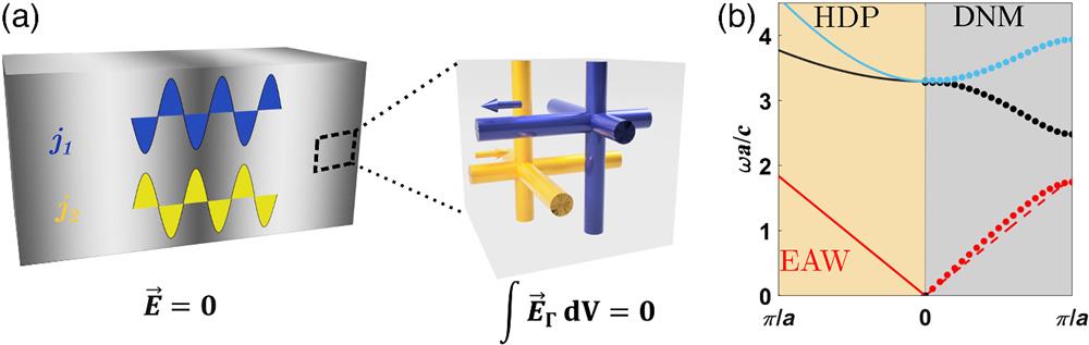
    Fig. 1. (a) Schematic diagram of the EAW mode in the HDP fluid. Blue and yellow curves represent the two counterpropagating charge carriers, resulting in a vanishing field. DNMs consist of two interwoven percolating metallic nets supporting the two opposing currents, analogous to the two counterpropagating carriers in the HDP. In the electrostatic limit, DNMs are equivalent to HDPs, with a homogenized EM field that vanishes at the Γ point. (b) Dispersion relation of an HDP with κ1,2=13, featuring a light-like EM wave (EMW) (cyan solid line), a longitudinal Langmuir wave (LMW) (solid black line), and the EAW (solid red line). The corresponding band structure of the unperturbed DNM is shown on the right, illustrating that the three modes resemble those of the HDP. The slope of the fundamental band (dashed red line) is in good agreement with the HDP theoretical model.
    (a) Magnitude of the electric field for the homogenized longitudinal EAW band components along the Γ−X direction. The three curves correspond to DNMs with paramter sets of P=(0.4 ,0.4 ,a2) (black line), P=(0.4 ,0.4 ,a3) (blue line), and P=(0.4 ,0.1 ,a2) (red line). (b) Schematic diagram of a DNM slab with finite thickness embedded in a vacuum. The BICs on the Γ point are decoupled from vacuum radiation and only weakly couple when the wave vector deviates from the Γ-point. (c) In-plane bandstructure of a DNM with P=(0.4 ,0.4 ,a2) slab. The DNM slab extends over N=5 unit cells in z-direction. The solid black lines are quasi-BIC states of EAW modes that weakly couple to vacuum radiation above the light line. The first black solid line below the light line is made of an in-plane EAW wave and therefore resembles the bulk dispersion, while the upper four black solid lines correspond to EAW standing waves. BICs exist at the Γ-point and are marked by red pentagrams. The two cyan lines are spoof plasmon surface modes. The region outside of the light cone is shaded in gray. (d) Corresponding heatmap of the transmissivity for an incoming plane wave from one side of the slab within the light cone. The reflectivity is 1, except close to the EAW standing wave bands, which leads to a Fabry–Pérot-like behavior with a high Q-factor that rapidly reaches infinity at the Γ-point. (e) Frequency of the BIC modes at the Γ-point as a function of the number of unit cells N in the DNM slab in z-direction. The black dots are calculated by full-wave simulations, and the blue points, connected by a dashed line that serves as a guide to the eye, are from the HDP model under hard wall boundary conditions.
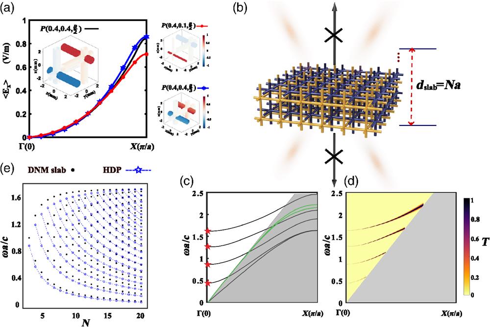
    Fig. 2. (a) Magnitude of the electric field for the homogenized longitudinal EAW band components along the ΓX direction. The three curves correspond to DNMs with paramter sets of P=(0.4,0.4,a2) (black line), P=(0.4,0.4,a3) (blue line), and P=(0.4,0.1,a2) (red line). (b) Schematic diagram of a DNM slab with finite thickness embedded in a vacuum. The BICs on the Γ point are decoupled from vacuum radiation and only weakly couple when the wave vector deviates from the Γ-point. (c) In-plane bandstructure of a DNM with P=(0.4,0.4,a2) slab. The DNM slab extends over N=5 unit cells in z-direction. The solid black lines are quasi-BIC states of EAW modes that weakly couple to vacuum radiation above the light line. The first black solid line below the light line is made of an in-plane EAW wave and therefore resembles the bulk dispersion, while the upper four black solid lines correspond to EAW standing waves. BICs exist at the Γ-point and are marked by red pentagrams. The two cyan lines are spoof plasmon surface modes. The region outside of the light cone is shaded in gray. (d) Corresponding heatmap of the transmissivity for an incoming plane wave from one side of the slab within the light cone. The reflectivity is 1, except close to the EAW standing wave bands, which leads to a Fabry–Pérot-like behavior with a high Q-factor that rapidly reaches infinity at the Γ-point. (e) Frequency of the BIC modes at the Γ-point as a function of the number of unit cells N in the DNM slab in z-direction. The black dots are calculated by full-wave simulations, and the blue points, connected by a dashed line that serves as a guide to the eye, are from the HDP model under hard wall boundary conditions.
    (a) Q-factor as a function of the asymmetry parameter α. The two methods of symmetry breaking are illustrated in the upper-right corner (represented by green hexagonal stars) and the lower-left corner (represented by red diamonds). In both cases, the Q-factor closely follows an inverse quadratic power law Q(α)=Q0α−2 (solid line). (b) Band structure of DNM supercell slabs. Dashed lines correspond to an unperturbed DNM slab, back-folded into the supercell Brillouin zone, while the thick solid lines show the perturbed case. The line color encodes the Q-factor. The lower four bands with kz=0 correspond to back-folded modes originating from the in-plane EAW bands, initially outside the light cone. The upper three modes have kz=π. The fifth band corresponds to the unperturbed BIC state at Γ, while the upper two bands are back-folded EAW standing waves. (c) Electric field distribution for the fifth band at Γ in the perturbed DNM supercell slab with N=2 and 8 unit cells in the y direction with a random offset between the two nets. The ultrahigh Q-factor persists even though the supercell lattice constant allows coupling into the first diffraction order.
    Fig. 3. (a) Q-factor as a function of the asymmetry parameter α. The two methods of symmetry breaking are illustrated in the upper-right corner (represented by green hexagonal stars) and the lower-left corner (represented by red diamonds). In both cases, the Q-factor closely follows an inverse quadratic power law Q(α)=Q0α2 (solid line). (b) Band structure of DNM supercell slabs. Dashed lines correspond to an unperturbed DNM slab, back-folded into the supercell Brillouin zone, while the thick solid lines show the perturbed case. The line color encodes the Q-factor. The lower four bands with kz=0 correspond to back-folded modes originating from the in-plane EAW bands, initially outside the light cone. The upper three modes have kz=π. The fifth band corresponds to the unperturbed BIC state at Γ, while the upper two bands are back-folded EAW standing waves. (c) Electric field distribution for the fifth band at Γ in the perturbed DNM supercell slab with N=2 and 8 unit cells in the y direction with a random offset between the two nets. The ultrahigh Q-factor persists even though the supercell lattice constant allows coupling into the first diffraction order.
    (a) Schematic diagram of a DNM microcavity of length L. (b) The fundamental modes are formed by EAW standing waves and are characterized by discrete reciprocal vectors marked through red, blue, and yellow balls. (c) The three fundamental mode frequencies as a function of L. The dashed lines are the HDP predictions, and the solid thick lines are the simulated DNM resonator states. The color encodes the Q-factor. (d) SC as a function of frequency for an L=12.5 mm DNM resonator. (e) Electric field distribution in the DNM microcavity at the resonance frequency (left) and away from the resonance (right).
    Fig. 4. (a) Schematic diagram of a DNM microcavity of length L. (b) The fundamental modes are formed by EAW standing waves and are characterized by discrete reciprocal vectors marked through red, blue, and yellow balls. (c) The three fundamental mode frequencies as a function of L. The dashed lines are the HDP predictions, and the solid thick lines are the simulated DNM resonator states. The color encodes the Q-factor. (d) SC as a function of frequency for an L=12.5  mm DNM resonator. (e) Electric field distribution in the DNM microcavity at the resonance frequency (left) and away from the resonance (right).
    Wenhui Wang, Antonio Günzler, Bodo D. Wilts, Ullrich Steiner, Matthias Saba. Unconventional bound states in the continuum from metamaterial-induced electron acoustic waves[J]. Advanced Photonics, 2023, 5(5): 056005
    Download Citation