
Petrisor Gabriel Bleotu, Radu Udrea, Alice Dumitru, Olivier Uteza, Maria-Diana Mihai, Dan Gh Matei, Daniel Ursescu, Stefan Irimiciuc, Valentin Craciun. Exploring fs-laser irradiation damage subthreshold behavior of dielectric mirrors via electrical measurements[J]. High Power Laser Science and Engineering, 2024, 12(2): 02000e15
- High Power Laser Science and Engineering
- Vol. 12, Issue 2, 02000e15 (2024)
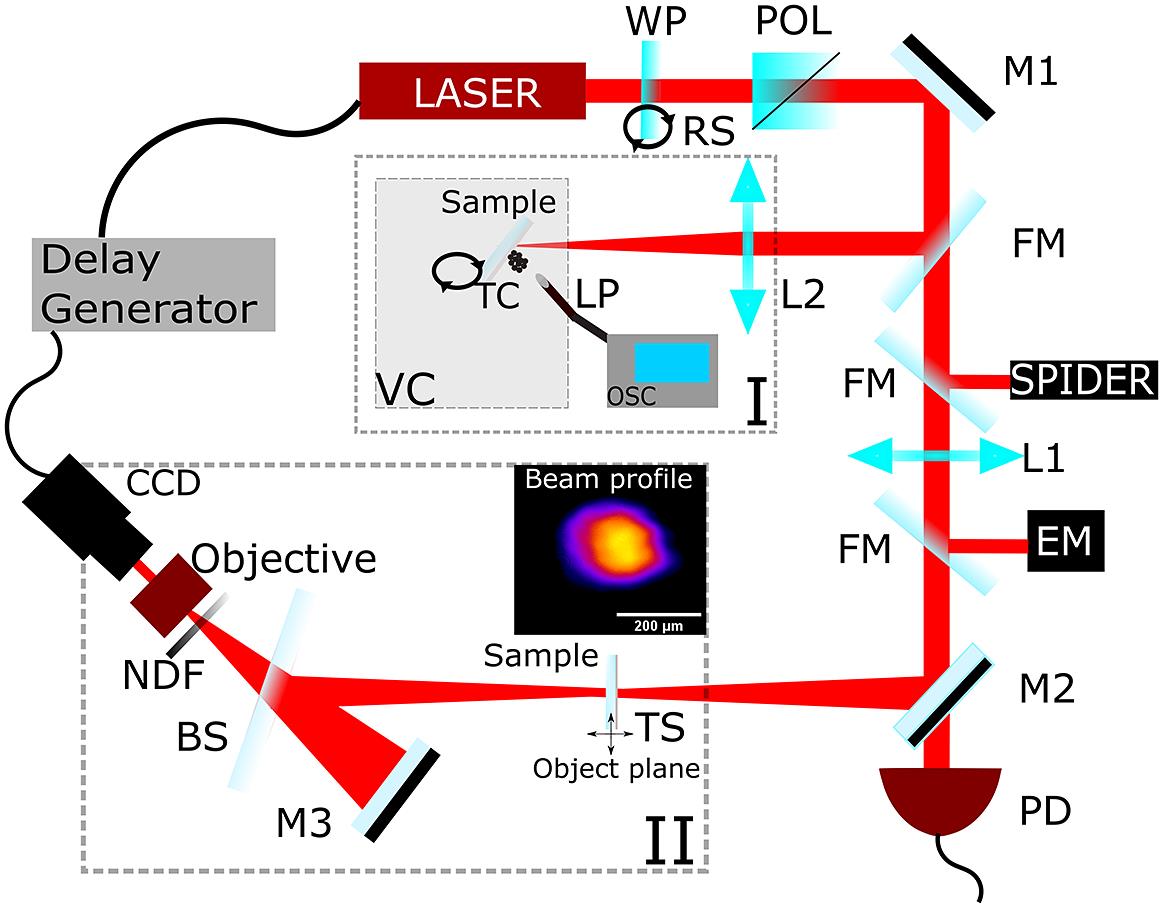
Fig. 1. Experimental setup. BS, beam splitter; EM, energy meter; FM, flip mirror; LASER, Ti:sapphire; L1 and L2, focusing lenses; LP, Langmuir probe; M1, high-reflection mirrors; M2, 99 -reflection mirror; M3, spherical mirror; NDF, neutral density filter; OSC, oscilloscope; POL, polarizer; PD, photodiode; TC, target current; TS, translation stage; RS, rotation stage; VC, vacuum chamber; WP, half-waveplate. The inset illustrates the input beam profile used for
 A  calculation.
-reflection mirror; M3, spherical mirror; NDF, neutral density filter; OSC, oscilloscope; POL, polarizer; PD, photodiode; TC, target current; TS, translation stage; RS, rotation stage; VC, vacuum chamber; WP, half-waveplate. The inset illustrates the input beam profile used for calculation. 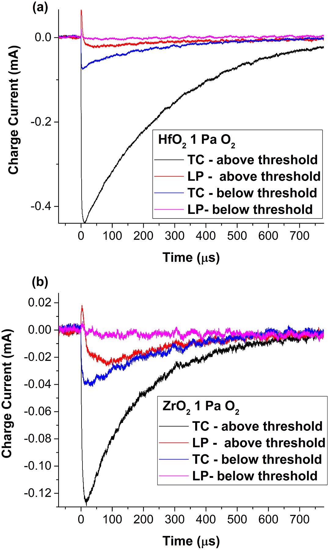
Fig. 2. Transient currents recorded during fs irradiation of  (a) and
  (b) films.
(a) and (b) films. Fig. 3. Calculated ion (a) and electron densities (b) ejected from the  films upon fs-laser irradiation above the ablation threshold fluence.
films upon fs-laser irradiation above the ablation threshold fluence. Fig. 4. LP total collected charge (a) and target total emitted charge (b) as functions of the laser fluence calculated for  films.
films. Fig. 5. (a) In situ microscopy images recorded with the imaging system and (b) ex situ microscope images of  and
and  irradiated samples recorded before irradiation (left), after the 1-on-1 (middle) and after the R-on-1 LIDT damage tests (right). The color bar of (a) maps the local fluence (
 ) inferred from energy measurement and pixel values.
and irradiated samples recorded before irradiation (left), after the 1-on-1 (middle) and after the R-on-1 LIDT damage tests (right). The color bar of (a) maps the local fluence () inferred from energy measurement and pixel values. Fig. 6. Comparison of the LIDT values determined from ex situ microscopy and the LP-TC approach for  (a) and
  (b) films fabricated in 0.8 Pa
  .
.
(a) and (b) films fabricated in 0.8 Pa . Fig. 7. LIDT value calculated from ex situ microscopy and the LP-TC method as a function of the metal-to-oxide ratio for the  and
and  samples.
and samples. Fig. 8. Comparison between the LIDT fluence predicted for a very large number of shots and the value obtained with electrical measurements, for films of  (a) and
  (b) obtained in different oxygen background pressures. The LIDT values determined by the irradiation of one site with multiple laser pulses are shown with dots. The solid lines are obtained by fitting these values with an analytical function. The dashed horizontal lines indicate the values obtained with electrical methods.
(a) and (b) obtained in different oxygen background pressures. The LIDT values determined by the irradiation of one site with multiple laser pulses are shown with dots. The solid lines are obtained by fitting these values with an analytical function. The dashed horizontal lines indicate the values obtained with electrical methods. 
Set citation alerts for the article
Please enter your email address
© Copyright 2018-2021 | Chinese Laser Press. All Rights Reserved 沪ICP备15018463号-20