Tianyue Hou, Yi An, Qi Chang, Pengfei Ma, Jun Li, Liangjin Huang, Dong Zhi, Jian Wu, Rongtao Su, Yanxing Ma, Pu Zhou, "Deep-learning-assisted, two-stage phase control method for high-power mode-programmable orbital angular momentum beam generation," Photonics Res. 8, 715 (2020)
Copy Citation Text
High-power mode-programmable orbital angular momentum (OAM) beams have received substantial attention in recent years. They are widely used in optical communication, nonlinear frequency conversion, and laser processing. To overcome the power limitation of a single beam, coherent beam combining (CBC) of laser arrays is used. However, in specific CBC systems used to generate structured light with a complex wavefront, eliminating phase noise and realizing flexible phase modulation proved to be difficult challenges. In this paper, we propose and demonstrate a two-stage phase control method that can generate OAM beams with different topological charges from a CBC system. During the phase control process, the phase errors are preliminarily compensated by a deep-learning (DL) network, and further eliminated by an optimization algorithm. Moreover, by modulating the expected relative phase vector and cost function, all-electronic flexible programmable switching of the OAM mode is realized. Results indicate that the proposed method combines the characteristics of DL for undesired convergent phase avoidance and the advantages of the optimization algorithm for accuracy improvement, thereby ensuring the high mode purity of the generated OAM beams. This work could provide a valuable reference for future implementation of high-power, fast switchable structured light generation and manipulation.
1. INTRODUCTION
After the first proposal of orbital angular momentum (OAM) in light beams by Allen et al. in 1992 [1], OAM-carrying beams with helical phase structure have been widely investigated and significantly developed, due to their widespread applications [2–5]. Some of these applications include free-space optical communication [6–8], super-resolution imaging [9], optical manipulation [10–12], and laser–matter interaction [13–15]. In order to meet the requirements of these applications, the generation of OAM beams has attracted a significant amount of attention [3,16], which has led to remarkable progress in this field. To date, various approaches for generating OAM beams have been proposed, which include two main categories [3]. One approach is the mode conversion approach, a straightforward approach that converts fundamental Gaussian beams to OAM beams via converters such as spatial light modulators [17,18], q-plates [19], and metamaterials [20]. The other approach is the intra-cavity approach, which involves intra-cavity elements that force the oscillator to resonate on a specific mode [21]. However, because of the limitation on the power handling ability of the converters or elements, these approaches have difficulty in generating high-power (kilowatt-level) OAM beams. Furthermore, dynamically switching the OAM mode is challenging. As a widely studied technology, coherent beam combining (CBC) could break the power limitation of a single laser beam while maintaining good beam quality [22–29]. In addition, due to the high rate of electro-optic phase modulators, the piston phase of the combining element can be switched at a high frequency (approximately gigahertz) [30]. This technology opens up opportunities for generating high-power and fast switchable OAM beams, which are strongly required in particular applications such as laser ablation [31], nonlinear frequency conversion [32], and satellite-to-ground communications [33].
In recent years, several theoretical studies of the use of CBC technology to generate OAM beams have been carried out, including the formation of optical vortices [34–36], the propagation properties of the combined OAM beams [37–39], and the OAM density distribution [40]. Considering that the combined beams are supposed to have a helical phase front, the breakthrough from theory to experiment depends on the proposal of the new phase control scheme. In 2013, Lachinova and Vorontsov proposed a phase control scheme based on the interference information of adjacent beams before collimated emissions [41]. Aksenov et al. experimentally confirmed this scheme by using a six-element fiber array; they effectively generated vortex beams of OAM +1 and OAM –1 [42]. In 2015, a different phase control scheme based on the interference information of the far field was proposed by Chu et al. [35], which Zhi et al. validated based on a six-element fiber array [43]. It can be seen that the generation of low-order OAM beams has been experimentally fulfilled, although increasing the number of laser array elements used to generate higher-order OAM beams still requires a more efficient phase control approach. Quite recently, we proposed a phase control concept that uses the information of the non-focal plane [44]. Using an optimization algorithm fed at the non-focal plane, we effectively solved the difficulty caused by the conjugated phase distributions and ensured the extension of the phased array elements. As a result, the stable generation of higher-order OAM beams could be realized. However, it is extremely difficult to achieve flexible and programmable switching, as different OAM modes usually correspond to different positions of the non-focal planes. Drawing on the recent progress in deep-learning (DL) in CBC [45,46], we are inspired to include a convolutional neural network (CNN) that assists the phase control, which is compatible with optimization algorithms. When compared to conventional optimization methods, CNNs can extract more features from the optical field information of a fixed plane, and thus the difficulty in programmable mode switching is solved.
In this paper, we present a DL-assisted, two-stage phase control method for generating high-power mode-programmable OAM beams. In the first stage, the phase errors are primarily compensated by a well-trained DL network constructed at a fixed non-focal plane. In the second stage, the residual phase errors are further compensated by an optimization algorithm that uses the intensity information from the focal plane. The performances of the first and second stages of phase compensation, as well as the OAM mode purity of the generated OAM beams, are theoretically studied to demonstrate the feasibility of the proposed method. By modulating the expected phases of the array elements and cost function, all-electronic flexible mode switching of the generated OAM beam is realized.
Sign up for Photonics Research TOC. Get the latest issue of Photonics Research delivered right to you!Sign up now
2. PRINCIPLE AND METHOD
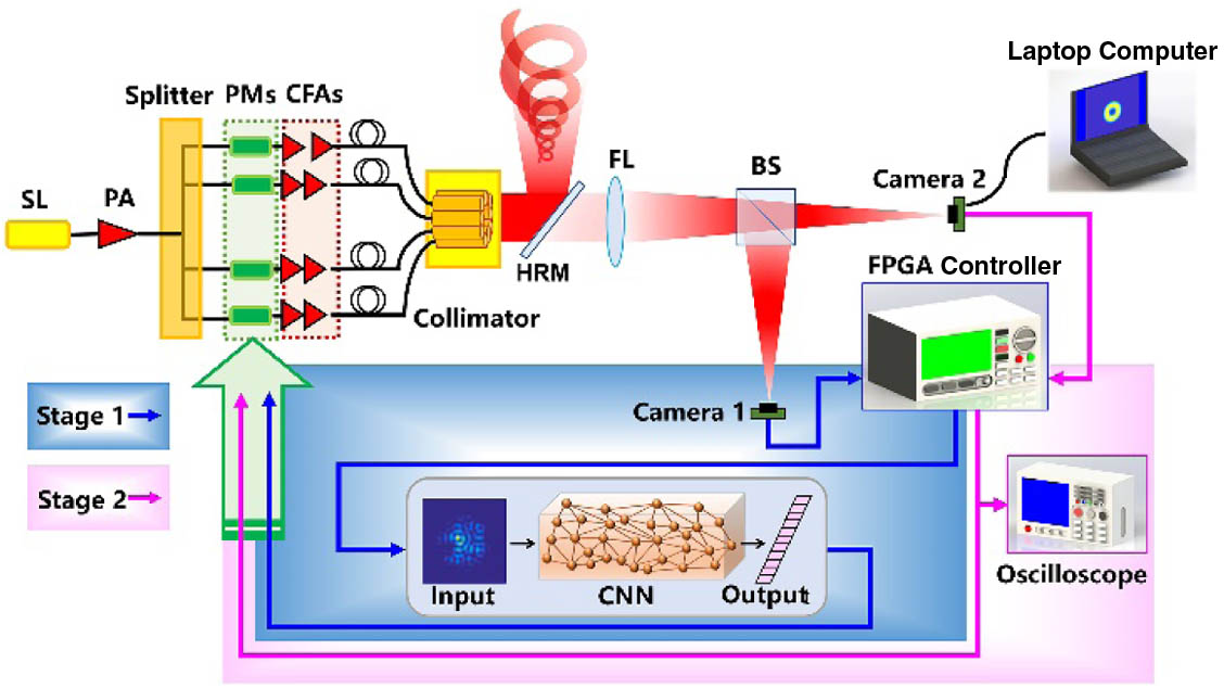
Figure 1 shows the scheme of the DL-assisted, two-stage phase control method. The first stage of our method estimates and compensates the phase errors of the CBC system based on a well-trained CNN, which is constructed at a fixed non-focal plane to ensure its performance and avoid convergence to an undesired optimum in the following stage. Subsequently, by using the optical field information from the focal plane, the residual phase errors are further compensated by the optimization algorithm in the second stage; hence, the accuracy of the phase locking is improved. A tiled aperture CBC system consists of beamlets. The linearly polarized seed laser (SL) output is amplified by a pre-amplifier (PA), which is split and sent through phase modulators (PMs). Subsequently, the laser beam from each PM passes through a series of cascaded fiber amplifiers (CFAs). After power scaling, the laser beams are emitted through a collimator array (which is always ring-shaped for generating OAM beams) to propagate in free space. The collimated beam array is split into two parts by a highly reflective mirror (HRM). The transmission part propagates through a focus lens (FL) prior to being sampled by a beam splitter (BS) for joint feeding of the phase control system at the non-focal and the focal plane, respectively. Specifically, our phase control scheme consists of two stages, i.e., (i) estimating and compensating the phase errors via a CNN and (ii) further compensating the residual phase errors by using an optimization algorithm. The intensity profile of the combined beam collected by camera 1, located at the non-focal plane, is sent to the field-programmable gate array (FPGA) controller to perform the first stage, while the intensity profile collected by camera 2, located at the focal plane, is also sent to the FPGA controller to perform the second stage. The FPGA controller carries a well-trained CNN and optimization algorithm that performs the two stages continuously and applies control voltages to the PMs to achieve phase locking.
Figure 1.Scheme of the DL-assisted, two-stage phase control method for CBC. SL, seed laser; PA, pre-amplifier; PM, phase modulator; CFAs, cascaded fiber amplifiers; HRM, highly reflective mirror; FL, focus lens; BS, beam splitter.
The complex amplitude of the -element collimated fundamental-mode Gaussian beam array at the source plane is given by where () is the coordinate of the source plane and (), , , , and account for the position, amplitude, waist width, piston phase, and aperture diameter of the th beamlet, respectively. The piston phases of array elements constitute an -dimensional relative phase vector When the configuration and parameters of the beam array are determined, the relative phase vector determines the optical field of the combined beam. Under the paraxial approximation, the complex amplitude and intensity profiles of the combined beam at can be expressed as where () represents the coordinate of the receiver plane and , and denote the wavelength, focal length, propagating distance, and the Fourier transform operation, respectively. Compared with and , the distance between the collimator array and the FL can be neglected. In the CBC systems, dynamic phase noise always exists. The aim of the phase control method is to compensate the phase errors and lock the relative phases to the expected values . Therefore, if the control system has learned the mapping relationship between the relative phase vector and intensity profile (of a certain plane) of the combined beam, the phase errors would be compensated directly.
In terms of our previous studies, we could make use of a CNN modified from the VGG-16 model [47,48] to learn that mapping relationship. The CNN consists of convolutional layers, max pooling layers, and fully connected layers. Unlike the original VGG-16 model, we change the filter size of the first convolutional layer from to and replace the Softmax function with the Sigmoid function. This CNN can capture the global structure of the input pattern such as the contour and intensity distribution, so it is insensitive to the noise signals and the digitization form of CCD cameras [48]. To efficiently estimate the phase errors, the CNN should be constructed and trained at the non-focal plane. The network learns to estimate relative phases from a single intensity pattern image of the combined beam at the non-focal plane (). The intensity patterns, as the samples for training, are generated by randomly changing the dimensional label vector. The label vector consists of the last items of the relative phase vector .
In the training procedure, the input images are passed through the layers of the CNN and regressed into an dimensional output vector. We define the loss of the CNN as the mean square error (MSE) between the output and label vectors, expressed as where denotes the order of the sample and , account for the output and label vectors of the CNN, respectively. Then the parameters of CNN are updated iteratively using back-propagated gradients based on the MSE loss. When the CNN achieves convergence, it could estimate the relative phases of array elements. Taking an intensity pattern image with the phase errors ) as input, the CNN output is an dimensional vector from which the -dimensional estimated relative phase vector can be obtained. In the first stage, the well-trained CNN could be used for real-time phase compensation, i.e., sending phase control signals to the phase modulators.
In the second stage, the residual phase errors could be further compensated via optimization algorithms to improve the accuracy of phase locking. As a typical optimization algorithm, the stochastic parallel gradient descent (SPGD) algorithm has been widely implemented in adaptive optics systems including CBC systems [25,49,50]. In this work, we take the SPGD algorithm as an example. Unlike conventional CBC phase control methods, which focus on controlling the phases of the array elements to a small fraction of , the DL-assisted, two-stage phase control method could flexibly lock the phases of the array elements to a variety of expected values to generate various structured light fields. Additionally, conventional cost functions such as the Strehl ratio and the power in the bucket are not sufficient for a more general phase control method. Drawing on our previous work, the power in the generalized “bucket” (PIGB) could be efficiently used as the cost function, which is expressed as [44] where with the parameter (where ) denotes an area of the focal plane where the proportion of the intensity and peak intensity is over (at the condition of ). The cost function represents the instantaneous power in the area, and is the instantaneous relative phase vector. In the second stage of the phase control method, the SPGD algorithm is used and the phase control signals continually update to make the cost function evolve until it reaches its extremum. It is worth noting that the cost function is the PIGB of the focal plane, and in contrast with the PIGB of the non-focal plane we used in our previous work [44], the shape of the area at the focal plane is more regular (for generating OAM beams, the area is approximately ring-shaped). Due to the first-stage phase compensation, using the PIGB of the focal plane as the cost function will not cause the phases of the beamlets to converge to the unexpected conjugated case.
To conclude, the first-stage phase control, based on the CNN, has the advantage of avoiding convergence to the local optimum in the optimization algorithm, while the second-stage phase control, based on the SPGD algorithm, could achieve more accurate phase locking. Therefore, the two-stage phase control method could realize the generation and programmable switching of complex light fields based on the CBC system.
3. RESULTS AND DISCUSSION
In this section, we study the performance of the DL-assisted, two-stage phase control method. Without loss of generality, a 12-element radial beam array, as shown in Fig. 2, is taken as an example. The parameters of the tiled aperture CBC system are , , , and . The position of the th-order beamlet is given by and , where is the radius of the ring. In the CBC system, according to our previous theoretical work, the non-focal plane is set 0.3 m behind the focal plane to extract more features of the optical field [44]. We first investigate the training process of the CNN and the preliminary compensated intensity profiles to show the performance of the first-stage phase compensation. We then study the convergence process of the optimization algorithm in the second stage to demonstrate the ability of our method to generate mode-programmable OAM beams. Finally, we discuss the characteristics of the phase control method in detail.
Figure 2.Schematic of the input radial laser array used for generating OAM beams.
The DL-assisted first-stage phase control aims to avoid the local optimum and save the convergence steps of the second-stage phase control. The performance of this preliminary compensation depends on the accuracy of the trained CNN, which we now investigate. The training process is performed on a desktop computer with an Intel Core i7-8700 CPU and GTX 1080 GPU. We have trained the CNN for 30 epochs with 150,000 prepared samples at the non-focal plane. These samples were acquired randomly via simulation. To investigate the convergence of the training process, we randomly generate 1000 additional testing samples. Figure 3 shows the calculated average MSE values of these 1000 testing samples after each training epoch. The calculated average MSE decreases from 2.21 at the first epoch to around 0.14 at the final epoch. Clearly, the CNN converges as the training process goes on.
Figure 3.Average MSE of the CNN as a function of training epochs.
Before we examine the results of the preliminary compensated intensity profiles, the expected relative phases for generating vortex beams of different topological charges (TCs) should be determined. If the TC of the generated OAM beam is , then the expected relative phase vector is expressed as Figures 4(a)–4(d) exhibit the expected phase distributions of the laser array for generating OAM , OAM , OAM , and OAM beams, respectively. In the first-stage phase control, the beam pattern with phase errors is collected and sent to the well-trained CNN, which will output the estimated relative phase vector . The phase control signals are then determined and sent to the phase modulators. As an example, we study the optical fields of the combined OAM beams at the focal plane. Figures 5(a1)–5(a6) and 5(b1)–5(b6) exhibit the intensity and phase distributions, respectively, of the combined beams with random phase errors. Figures 5(c1)–5(c6) and 5(d1)–5(d6) show the intensity and phase distributions, respectively, of the combined beams that have been preliminarily compensated based on the DL network. It can be seen that the intensity profiles of the combined beams, after the first-stage phase compensation, have main rings with helical wavefronts of . However, the non-uniform characteristic of the intensity distribution along the angular direction and the distortion in the wavefront were observed. Hence, we can conclude that the convergent CNN can efficiently compensate a considerable part of the phase errors, while the residual phase errors require further compensation by the second-stage phase control.
Figure 4.Expected phase distributions of the laser array for generating (a) OAM , (b) OAM , (c) OAM , and (d) OAM beams.
Figure 5.Performance of the first-stage phase compensation based on the DL network. (a1)–(a6) Intensity profiles and (b1)–(b6) phase distributions of the combined beams with random phase errors. (c1)–(c6) Intensity profiles and (d1)–(d6) phase distributions of the combined beams after first-stage phase compensation.
Based on the completion of the first-stage phase control, the SPGD algorithm is implemented to further compensate the residual phase errors. Substituting Eq. (6) into Eq. (5), and with the condition of , we obtain the integral area () for calculating the cost function () during the operation of the SPGD algorithm. Note that the switching of the cost function is easily programmed and implemented in CBC systems.
Figures 6(a) and 6(b) exhibit the integral area () for generating OAM and OAM beams, respectively. Therefore, we should not be surprised to find that the conjugated expected phase vectors share the same generalized “bucket,” because the intensity profiles at the focal plane are the same for generating OAM and OAM beams. In our previous work, we demonstrated that by utilizing the SPGD algorithm for phase locking, the cost function extracted at the focal plane would cause a 50% probability for generating an OAM beam with an unexpected TC. In this work, the phase control system is improved by introducing the DL method; thus, this challenge is expected to be solved.
Figure 6.Generalized “buckets” with for calculating the cost function to generate (a) OAM and (b) OAM beams.
Figure 7 shows the results of generating OAM beams with different TCs based on the proposed phase control method. For each case, 100 simulations were performed. As depicted in Figs. 7(a)–7(d), the cost function always converged within 100 steps and the case for being trapped in local optima did not occur. In addition, the average intensity and phase distributions of the combined beams after the two-stage phase control of 100 simulations are quite similar to the CBC system without phase errors. To further analyze the performance of the phase control method, we have simulated the evolution of the relative phases of array elements during the 100 simulations.
Figure 7.Generation of OAM beams. (a)–(d) Convergence curves of the cost functions for generating OAM , , , and beams, respectively. One hundred simulations have been performed for each case. The inset figures show the average intensity (left) and phase (right) distributions of the generated OAM beams.
In Fig. 8, from left to right, the TCs of the generated OAM beams are , , , and . The three rows correspond to the laser array with random phase errors, after the DL-assisted phase compensation (the first stage), and after the SPGD-based phase compensation (the second stage). Most of the phase errors were compensated by the first-stage phase compensation, while the phase-compensation residuals of several groups are obvious. The second-stage phase control efficiently compensated for the residual phase errors and further improved the phase locking accuracy. Furthermore, the results indicate that the DL-assisted, two-stage phase control method could avoid the confusion caused by the conjugated phase distributions. As we have mentioned above, OAM and OAM beams have the same far-field intensity profiles; therefore, when the cost function takes its maximum value, it corresponds to two conjugated phase distributions. Prior to the second stage of our method, the phase errors had been preliminarily compensated by the CNN, and the combined beam is similar to the expected OAM beam. Therefore, our method guarantees the avoidance of the undesired optimum and ensures that the TC of the combined beam converges to a definite value. By programming and modulating the generalized “bucket” and the expected phase vector, the OAM mode of the generated OAM beam can be flexibly switched. An illustrative video of programmable OAM mode switching using the two-stage phase control method is shown in Visualization 1.
Figure 8.Phases of the array elements during 100 simulations. From top to bottom, they are the laser array with random phase errors, after the first-stage phase compensation, and after the second-stage phase compensation. The first, second, third, and fourth columns correspond to the generation of OAM , OAM , OAM , and OAM beams, respectively.
From the above results, it is apparent that our DL-assisted, two-stage phase control method is feasible for the generation of OAM beams and the programmable switching of the OAM mode. The simulated results also indicate that the phase locking accuracy is improved after each stage of phase control. In this section, we take a closer look at the OAM mode purity of the generated OAM beams, which could reflect the accuracy of the phase control method. In the polar coordinate system, the optical field in Eq. (3) at the focal plane is given by where () and () are the coordinates of the source and focal plane, respectively. There is a phenomenon where the intensity pattern of the combined beam, generated from a tiled aperture CBC system, contains sidelobes. When our method is applied in practical settings, the sidelobes should be filtered out and the main ring of the generated OAM beam should be extracted. Using a programmable circular aperture, the truncated optical field is expressed as where represents the diameter of the truncated aperture, and for the cases of generating OAM and OAM beams, and , respectively. According to the definitions of OAM mode purity and OAM spectrum, the combined beam could be expanded as [51,52] The OAM mode purity , which corresponds to the th-order OAM mode, can be obtained as In terms of the results shown in Fig. 8, we substitute the phase vector into Eqs. (8)–(10), and then the average OAM spectra (simulated 100 times) of the combined beams can be obtained. We first investigate the case of generating OAM beams as an example. The average intensity profiles [e.g., Figs. 9(a1), 9(b1), 9(c1)] and phase distributions [e.g., Figs. 9(a2), 9(b2), 9(c2)] illustrate that the truncated combined beams are turning close to the ideal OAM beams during the phase control process. The calculated OAM spectra of the truncated combined beams with random phase errors, after first-stage phase compensation, and at the end of the two-stage phase control are shown in Figs. 9(a3), 9(b3), and 9(c3), respectively. It can be observed that after the first stage of phase control, the OAM mode purity has been greatly increased, to 0.94 on average. After the second stage of phase control, the average purity further increased to 0.99.
Figure 9.Analysis of the OAM mode purity of the truncated combined OAM beams. From top to bottom, the rows show the average intensity profiles, the average phase distributions, and the average OAM-spectra. From left to right, the cases are with random phase errors, after the first-stage phase compensation, and after the second-stage phase compensation.
Figure 10 presents the average OAM spectra of the truncated combined beams with other TCs before and after the second stage of phase control. For the cases of generating OAM [e.g., Figs. 10(a1) and 10(a2)], OAM [e.g., Figs. 10(b1) and 10(b2)], and OAM beams [e.g., Figs. 10(c1) and 10(c2)], the OAM mode purity of the expected TC increased from 0.95 to 0.99, 0.96 to 0.99, and 0.95 to 0.99, respectively. The increase in OAM mode purity illustrates the importance of the second-stage phase control. Additionally, we have shown that the generated OAM beams are of high purity, which indicates that the accuracy of our two-stage phase control method is high enough to generate OAM beams.
Figure 10.Average OAM spectra of the truncated combined OAM beams before and after the second-stage phase control. (a1), (b1), (c1) Cases of the truncated combined OAM , OAM , and OAM beams, respectively, before the second-stage phase control; (a2), (b2), (c2) cases of the truncated combined OAM , OAM , and OAM beams, respectively, after the second-stage phase control.
In a nutshell, the simulated results of the first- and second-stage phase control presented in Section 3.A and Section 3.B demonstrated the advantage of the DL-assisted first-stage phase control in avoiding undesired optima, while the analysis of the OAM mode purity in Section 3.C indicates that the optimization-algorithm-based second-stage phase control plays an important role in improving the phase locking accuracy. These advantages are unique to the DL-assisted, two-stage phase control method, which are extremely difficult to achieve using conventional phase control methods. Although we have only presented the typical case of a 12-element array, the phase control method has been proven to be highly useful in the coherent combining of different arrays for generating OAM beams with various TCs.
4. CONCLUSION
In this paper, we proposed a DL-assisted, two-stage phase control method and implemented the method in the tiled aperture CBC system to generate OAM beams. The performances of the first and second stages of the phase control method and the OAM mode purity of the generated OAM beams were analyzed. The results demonstrate that the phase control method combines the advantages of the DL network and the optimization algorithm by obtaining the desired values of the relative phases of array elements with high accuracy. By programming and modulating the expected phase vector and cost function, the OAM mode of the combined beam could be flexibly switched. The proposed phase control method offers an opportunity to generate high-power mode-programmable OAM beams based on CBC technology. It has the potential to guide the generation and manipulation of various structured light fields with complex intensity and phase distributions; therefore, further research should be conducted.
Acknowledgment
Acknowledgment. The authors are very thankful to Xiaoming Xi and Xugang Wu for valuable discussions.
Tianyue Hou, Yi An, Qi Chang, Pengfei Ma, Jun Li, Liangjin Huang, Dong Zhi, Jian Wu, Rongtao Su, Yanxing Ma, Pu Zhou, "Deep-learning-assisted, two-stage phase control method for high-power mode-programmable orbital angular momentum beam generation," Photonics Res. 8, 715 (2020)