
Juncheng Guo, Lin Lu, Chuanxin Wu, Baofu Zhang, Heng Wei, Xiaoyu Zhao. Time Delay Measurement Scheme for Radio-over-Fiber Link Based on Time-Frequency Signal Subcarrier Modulation[J]. Acta Optica Sinica, 2019, 39(12): 1206005
- Acta Optica Sinica
- Vol. 39, Issue 12, 1206005 (2019)
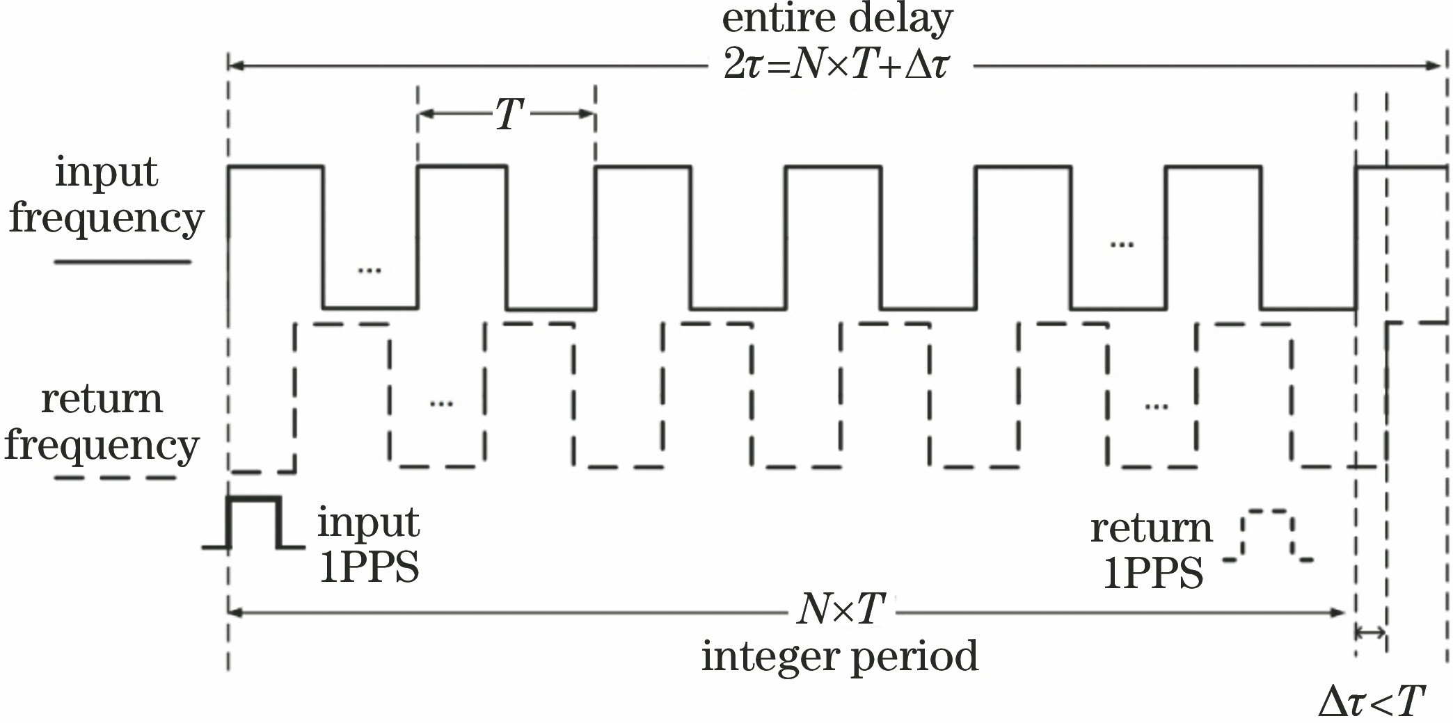
Fig. 1. Sequence diagram of time-delay measurement

Fig. 2. Principle of subcarrier modulation of 1PPS signal. (a) Frequency domain relation when ROF signal is baseband signal; (b) frequency domain relation when 1PPS signal is modulated to the center frequency of ROF signal; (c) the frequency-domain relation for the new time-frequency signal mixed transmission; (d) the frequency domain relation after the signal is transmitted to the receiving end and then photoelectric detection
Fig. 3. Scheme of time-delay measurement
Fig. 4. Waveforms of combined signal. (a) Original combined signal of 1PPS*+100 MHz+1.5 GHz; (b) combined signal in PIN detection
Fig. 5. Waveforms of time-frequency signals. (a) Restored 1PPS* signal; (b) restored 100 MHz signal
Fig. 6. Spectra of 1.5 GHz signal. (a) Directly mixed modulation; (b) subcarrier modulation
Fig. 7. Background time-delay of 25 km link. (a) Only with measurement links; (b) with ROF and measurement links
Fig. 8. EVMRMS of system
Fig. 9. Time delay of 25 km fiber link when temperature rises and falls. (a) Coarse value; (b) fine value; (b) FTD value
Fig. 10. Allen variance and EVMRMS of 1.5 GHz signal. (a) Allen variance; (b) EVMRMS of 1.5 GHz signal

Set citation alerts for the article
Please enter your email address
© Copyright 2018-2021 | Chinese Laser Press. All Rights Reserved 沪ICP备15018463号-20