• Journal of Infrared and Millimeter Waves
  • Vol. 40, Issue 6, 829 (2021)
Wei-Xin CUI1、*, Xiang LI2, Hao SUN1, Zeng-Chuang XU1, Yong LI1, and Yuan-Hang YU1
Author Affiliations
  • 1Shanghai Institute of Technical Physics,Chinese Academy of Sciences,Shanghai ,200083,China
  • 2Science and Technology on Special System Simulation Laboratory,Beijing Simulation Center,Beijing 100854,China
  • show less
    DOI: 10.11972/j.issn.1001-9014.2021.06.017 Cite this Article
    Wei-Xin CUI, Xiang LI, Hao SUN, Zeng-Chuang XU, Yong LI, Yuan-Hang YU. Area array infrared earth sensor heterogeneity non-uniformity correction design[J]. Journal of Infrared and Millimeter Waves, 2021, 40(6): 829 Copy Citation Text show less
    Schematic diagram of attitude sensitivity principle of infrared earth sensor (a) the geometric position relationship between, (b) the principle of attitude sensitivity infrared earth sensor and the earth space
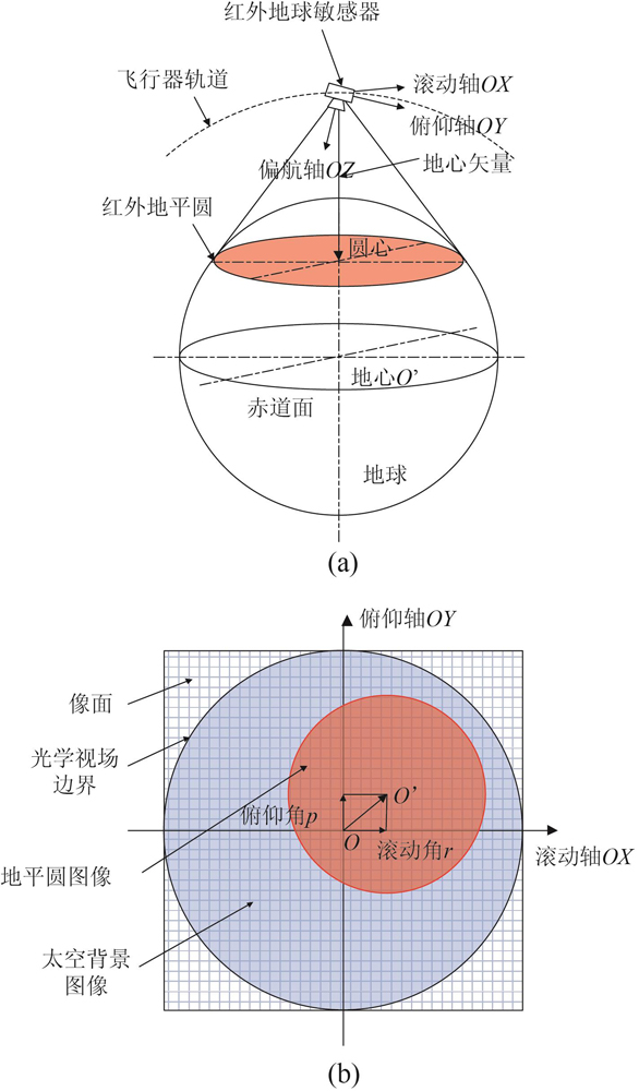
    Fig. 1. Schematic diagram of attitude sensitivity principle of infrared earth sensor (a) the geometric position relationship between, (b) the principle of attitude sensitivity infrared earth sensor and the earth space
    Schematic diagram of infrared earth sensor optical system
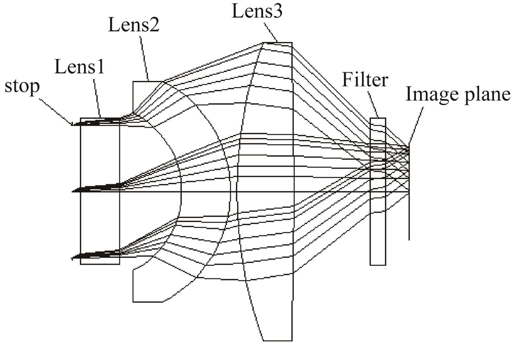
    Fig. 2. Schematic diagram of infrared earth sensor optical system
    Modulation transfer function
    Fig. 3. Modulation transfer function
    Radial energy distribution curve
    Fig. 4. Radial energy distribution curve
    Uniformity curve of image surface illuminance
    Fig. 5. Uniformity curve of image surface illuminance
    Working principle diagram of calibration components
    Fig. 6. Working principle diagram of calibration components
    Background images at different temperatures (a) 24.83 ℃,(b) 27.62 ℃,(c) 28.33 ℃,(d) 30.4 ℃
    Fig. 7. Background images at different temperatures (a) 24.83 ℃,(b) 27.62 ℃,(c) 28.33 ℃,(d) 30.4 ℃
    Corrected images at different temperatures (a) 27.62 ℃, (b) 28.33 ℃, (c) 30.4 ℃
    Fig. 8. Corrected images at different temperatures (a) 27.62 ℃, (b) 28.33 ℃, (c) 30.4 ℃
    Image of the on-orbit detector after correction
    Fig. 9. Image of the on-orbit detector after correction
    Image of the ground detector after correction
    Fig. 10. Image of the ground detector after correction
    Wavelength/μm14~16.25 μm
    Field±25°
    Entrance pupil diameter/mm8.66
    F/#0.8
    Focal length/mm5.1
    Back working distance/mm7.5
    Optical materialGE/ZNSE
    Total length/mm21.9
    Weight/g10
    Table 1. Optical system parameters
    温度24.83 ℃27.62 ℃28.33 ℃30.49 ℃
    非均匀度0.033 10.032 80.032 70.032 6
    Table 2. Non-uniformity of detector image at different temperatures
    温度27.62 ℃28.33 ℃30.49 ℃
    非均匀度0.001 00.001 30.002 0
    Table 3. Non-uniformity of detector image after correction at different temperatures
    1#2#
    在轨图像0.12140.1872
    地面图像0.12500.0991
    Table 4. Non-uniformity contrast between on-orbit image and the groud image
    Wei-Xin CUI, Xiang LI, Hao SUN, Zeng-Chuang XU, Yong LI, Yuan-Hang YU. Area array infrared earth sensor heterogeneity non-uniformity correction design[J]. Journal of Infrared and Millimeter Waves, 2021, 40(6): 829
    Download Citation