• Infrared and Laser Engineering
  • Vol. 50, Issue 5, 20200332 (2021)
Zhi Yu, Qingliang Meng, Feng Yu, Yunsong Nie, Zhenming Zhao, and Nan Guo
Author Affiliations
  • Beijing Institute of Space Mechanics & Electricity, Beijing 100094, China
  • show less
    DOI: 10.3788/IRLA20200332 Cite this Article
    Zhi Yu, Qingliang Meng, Feng Yu, Yunsong Nie, Zhenming Zhao, Nan Guo. Thermal design and test for space camera on inclined-LEO orbit[J]. Infrared and Laser Engineering, 2021, 50(5): 20200332 Copy Citation Text show less
    Schematic diagram of the camera configuration
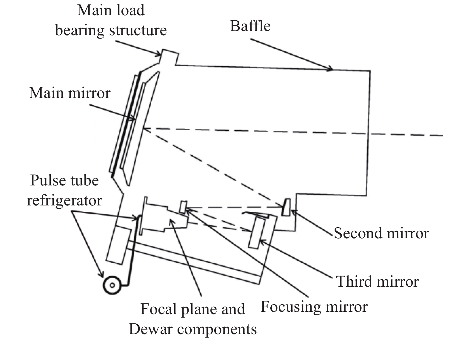
    Fig. 1. Schematic diagram of the camera configuration
    Periodic heat flow with different β angle (normal attitude)
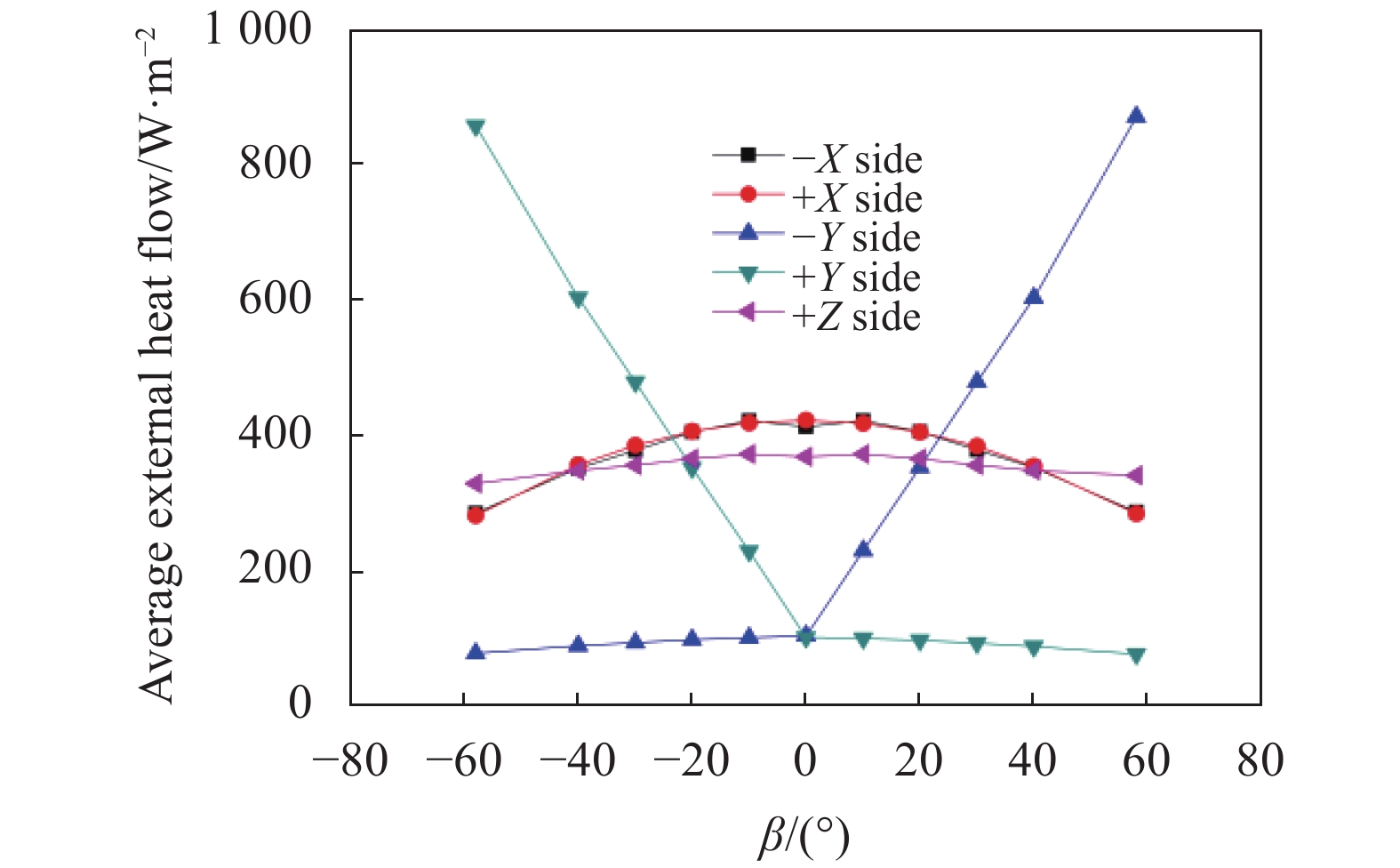
    Fig. 2. Periodic heat flow with different β angle (normal attitude)
    Periodic heat flow with different β angle (attitude maneuver)
    Fig. 3. Periodic heat flow with different β angle (attitude maneuver)
    Periodic heat flow absorbed by coupled radiating surface with different β angle
    Fig. 5. Periodic heat flow absorbed by coupled radiating surface with different β angle
    Schematic diagram of heat dissipation for pulse tube refrigerator
    Fig. 6. Schematic diagram of heat dissipation for pulse tube refrigerator
    Temperature variation curve of optical system in orbit
    Fig. 7. Temperature variation curve of optical system in orbit
    Temperature variation curve of Dewar window in orbit
    Fig. 8. Temperature variation curve of Dewar window in orbit
    ComponentsThermal control index
    Baffle−100-80 ℃
    Main load bearing structure10-24 ℃
    Main mirror, second mirror, third mirror(18±2) ℃,stability better than ±0.3 ℃/orbit
    Focusing mirror(18±1.2) ℃,stability better than ±0.3 ℃/orbit
    Pulse tube, refrigerator−35-15 ℃,stability better than ±5 ℃/orbit
    Dewar components>28 ℃ (Heating decontamination stage)
    Table 1. Thermal control index of the camera main components
    CaseOrbit external thermal fluxTemperature boundaryOperating mode
    Case 1MinimumLow temperature boundaryHeating decontamination mode
    Case 2MinimumLow temperature boundaryStandby mode
    Case 3MaximumHigh temperature boundaryNormal operation mode
    Table 2. Thermal balance test cases
    ComponentsThermal balance test/℃In orbit temperature/℃Temperature stability/℃·orbit−1Index satisfaction
    Case 2Case 3
    Main mirror18.6-18.719.3-19.618.7-18.9<±0.3
    Second mirror18.3-18.618.3-18.517.8-18.2<±0.3
    Third mirror18.8-18.918.9-19.118.7-18.9<±0.3
    Focusing mirror17.8-18.118.4-18.818.2-18.7<±0.3
    Baffle3.8-4.46.3-107.6-12.3
    Main load bearing structure16.8-19.717.2-20.417.1-20.2
    Refrigerator compressor−32.8- −31.9−13.2- −11.8−23.6- −18.3<±5
    Refrigerator hot end−32.2- −31.4−18.7- −11.6−15.8- −11.5<±5
    Table 3. Temperature data of thermal balance test and in orbit
    Zhi Yu, Qingliang Meng, Feng Yu, Yunsong Nie, Zhenming Zhao, Nan Guo. Thermal design and test for space camera on inclined-LEO orbit[J]. Infrared and Laser Engineering, 2021, 50(5): 20200332
    Download Citation