• Laser & Optoelectronics Progress
  • Vol. 57, Issue 21, 211403 (2020)
Wang Tao1, Qiao Weilin1, Wang Ning1, Zhang Jin1, Tang Jie1, Wang Hao2, and Wu Jun1、*
Author Affiliations
  • 1中国民航大学航空工程学院, 天津 300300
  • 2中国民航大学工程技术训练中心, 天津 300300
  • show less
    DOI: 10.3788/LOP57.211403 Cite this Article Set citation alerts
    Wang Tao, Qiao Weilin, Wang Ning, Zhang Jin, Tang Jie, Wang Hao, Wu Jun. Effect of Scanning Speed on Microstructure and Properties of Laser Cladding NiCoCrAlY Coating[J]. Laser & Optoelectronics Progress, 2020, 57(21): 211403 Copy Citation Text show less
    NiCoCrAlY alloy powder morphology
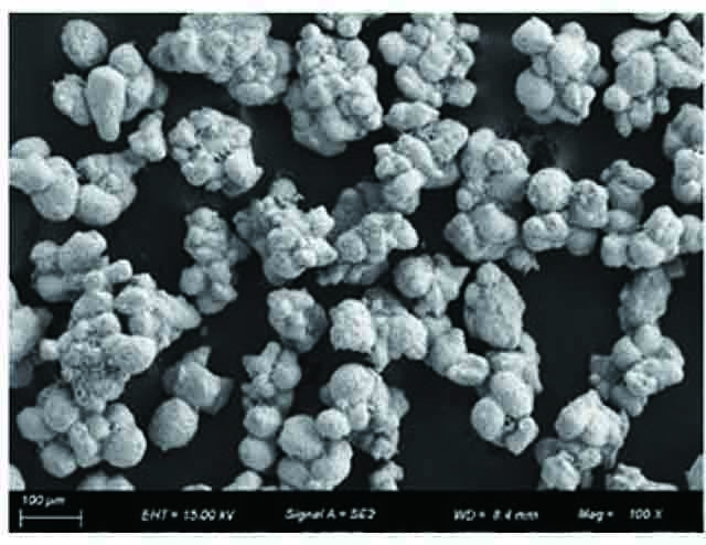
    Fig. 1. NiCoCrAlY alloy powder morphology
    Schematic of laser cladding test
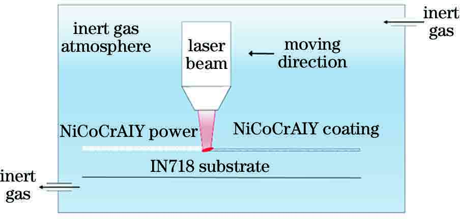
    Fig. 2. Schematic of laser cladding test
    Macroscopic morphology and cross section morphology of single NiCoCrAlY coating. (a1) (b1) 4 mm/s; (a2) (b2) 8 mm/s; (a3) (b3) 12 mm/s; (a4) (b4) 16 mm/s
    Fig. 3. Macroscopic morphology and cross section morphology of single NiCoCrAlY coating. (a1) (b1) 4 mm/s; (a2) (b2) 8 mm/s; (a3) (b3) 12 mm/s; (a4) (b4) 16 mm/s
    Influence of scanning speed on the forming of single NiCoCrAlY coating. (a) Height and width of coating; (b) dilution rate of coating
    Fig. 4. Influence of scanning speed on the forming of single NiCoCrAlY coating. (a) Height and width of coating; (b) dilution rate of coating
    Microstructure of single NiCoCrAlY coating. (a1)-(d1) Areas near top zones; (a2)-(d2) center zones; (a3)-(d3) bonding zones
    Fig. 5. Microstructure of single NiCoCrAlY coating. (a1)-(d1) Areas near top zones; (a2)-(d2) center zones; (a3)-(d3) bonding zones
    NiCoCrAlY coating hardness
    Fig. 6. NiCoCrAlY coating hardness
    Friction coefficient variation curves. (a) 4 mm/s; (b) 8 mm/s; (c) 12 mm/s; (d) 16 mm/s
    Fig. 7. Friction coefficient variation curves. (a) 4 mm/s; (b) 8 mm/s; (c) 12 mm/s; (d) 16 mm/s
    Wear rate
    Fig. 8. Wear rate
    SEM micrographs of wear tracks of NiCoCrAlY coating. (a) 4 mm/s; (b) 8 mm/s; (c) 12 mm/s; (d) 16 mm/s
    Fig. 9. SEM micrographs of wear tracks of NiCoCrAlY coating. (a) 4 mm/s; (b) 8 mm/s; (c) 12 mm/s; (d) 16 mm/s
    Wear tracks of NiCoCrAlY coating。(a) 3D profile; (b) depth curves of wear cross section
    Fig. 10. Wear tracks of NiCoCrAlY coating。(a) 3D profile; (b) depth curves of wear cross section
    ElementY2O3CoAlCrNi
    Mass fraction /%Technical requirement0.5-0.82.2-2.84-615.5-17.5Balance
    Detection result0.582.464.5216.94Balance
    Table 1. Chemical composition of NiCoCrAlY alloy powder
    ElementCSiMnPSCrNiCuMoTiCoAlNb+TaFe
    Mass fraction /%0.0650.180.190.0090.0119.4852.70.053.021.060.150.565.08Balance
    Table 2. Chemical composition of IN718 alloy
    NumberV /(mm·s-1)Mass fraction /%
    NiCoCrAlFe
    465.741.4318.162.487.61
    1864.021.2818.972.557.48
    1264.491.2418.492.717.54
    1665.191.3319.292.587.32
    464.871.3319.473.777.68
    2864.621.2718.963.568.25
    1263.881.1819.123.188.53
    1663.021.4318.913.128.32
    465.161.5319.162.539.76
    3863.831.2819.072.8910.49
    1265.421.1419.532.679.37
    1662.871.3319.472.7710.41
    Table 3. Contents of main elements of NiCoCrAlY coatings at four scanning speeds
    Wang Tao, Qiao Weilin, Wang Ning, Zhang Jin, Tang Jie, Wang Hao, Wu Jun. Effect of Scanning Speed on Microstructure and Properties of Laser Cladding NiCoCrAlY Coating[J]. Laser & Optoelectronics Progress, 2020, 57(21): 211403
    Download Citation